The Synthesizer Expander Module filter section represents a departure from the 24 dB "ladder" style filter often seen in vintage synths. Like the Oberheim SEM module it's based on, ours uses a 12 dB state-variable filter. This refers to its curves - it can function as a lowpass, bandpass, or highpass filter and features a knob allowing a continuous sweep from lowpass to highpass response (with "notch" filtering in the middle position). This gives it a great deal of flexibility, and the 12 dB curve gives it a brighter overall tonality than a typical ladder filter. The classic state variable filter generally sounds awesome, and our model of it really does it justice!
If you're not familiar with how filters work, a lowpass filter allows frequencies below the cutoff frequency setting to pass through, but blocks frequencies above the cutoff frequency. Highpass is the opposite of lowpass mode: high-frequency content remains, but low frequencies are removed as the cutoff frequency increases. Sliding the Bandpass switch enables Bandpass mode combining both lowpass and highpass modes, leaving sound only "in the middle." The cutoff frequency lies roughly halfway between the falloff on each side. A notch filter does the opposite - it removes a middle piece of the audio spectrum but leaves other frequencies intact. (That might not sound useful, but setting the filter to Notch mode and slowly sweeping the cutoff frequency with an LFO creates nifty phaser-like tones - great for imitating vintage string synths.)
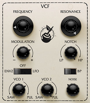
Frequency- Sets the frequency where frequency attenuation begins with its effect dependent upon the currently chosen lowpass/bandpass/notch/highpass/etc. filter mode.
Resonance- Emphasizes sound energy at and around the cutoff frequency by adding feedback from the filter's output back to its input. This is useful for creating commonly heard synth "wah" tones, especially when the cutoff frequency is modulated with an envelope generator or one of the LFO's.
Modulation amount knob and source switch- Applies modulation to the filter cutoff frequency. The mod amount knob is bidirectional; rotating it right from center position adds positive modulation, rotating it left adds negative modulation. Center position is off, i.e. no modulation.
The three-position slide switch selects the filter mod source from three sources:
Env 1 (VCO 1) / Env 2 (VCO 2)- Modulation source is envelope 1 or envelope 2. Selecting the envelopes as mod source doesn't "disconnect" them from the VCA or VCF.
Off- Disables mod.
LFO- Enables mod from the onboard LFO.
LP>HP/Notch control- Continuously varies the filter response from lowpass to highpass as the knob is rotated from left to right. The middle position creates a notch response.
BP (bandpass) switch- Alters the filter response to bandpass when engaged (i.e. combination of lowpass and highpass leaving frequencies "in the middle." The LP>HP knob is disabled and gets grayed when the BP switch is enabled.
VCO 1 / VCO 2 Saw/Pulse level- The VCO 1 and VCO 2 knobs adjust the volumes of the saw and pulse waves for VCO 1 and 2, respectively. These are bidirectional knobs as well - rotating them left from center position increase the saw wave level, rotating it right increase the volume of the pulse wave. Center position is off (if you're getting no sound, check these first).
Noise level- Sets the level of pink noise - the original instrument had a pink noise generator, not the more common white noise. For those of you keeping score at home, the random signal of pink noise represents each octave across the frequency spectrum equally, and sounds duller to the ear than white noise.