The original Polivoks filter is unquestionably its most unique feature - it boasts a truly unique, gnarly distorted tone. Although this certainly wasn't the intended outcome, the Polivoks filter is loved by many synthesists. Over the years, there have been numerous copies of its circuit in the hardware modular synthesis world, but up until now, it hasn't been emulated in the virtual synthesizer world.
The basic design was intended to emulate the 12dB/oct slope state-variable filters seen in Oberheim synths of the 70s and 80s. These are great-sounding filters and highly flexible as a result of their multiple modes (more on this later). Filters of this type made use of a still-relatively-new component called an "operational transconductance amplifier" or OTA. We'll assume that a lack of availability of fancy-pants OTAs in the Soviet Union during the 80s is what drove designer Vladimir Kuzmin to forego the OTA and instead make use of something called a "programmable op-amp" in its place. These were never intended for a variable filter application, but alas, Vladimir Kuzmin figured out a way to use it in such a manner, and thus, the raunchy Polivoks filter was born.
Also, we'd be remiss not to mention the nifty Envelope Generator Mode switch. This puts the Filter's ADSR envelope in looping mode, which essentially gains you an LFO, and it lets you create unique mod waveshapes. (The Amp section has this capability too, hooray!)
The Original Polivoks Filter vs. Atomika's Super-Duper New and Improved Filter
The controls for the original Polivoks filter are straightforward and similar to what you'd see in any garden-variety analog synth (cutoff frequency, resonance, envelope controls and depth, etc.). It does however have switchable lowpass and bandpass modes. However, Cherry Audio's Atomika goes WAY beyond, including the aforementioned lowpass and bandpass modes, plus highpass, notch, and peak modes. (see the Response control section below for the nitty gritty on exactly what each of these do) As you might imagine, these extra modes offer far more sounds than the original.
Furthermore, due to its unique design, our mad scientist DSP doctor Mark Barton discovered a few eccentric circuit behaviors along the way. Realizing these sounded pretty neat, these were incorporated into the design with the Starve and Filter Drive controls (as well as the Amp Drive knob in the Amp section). This all adds to up to even more of the idiosyncratic filter sound of Atomika.
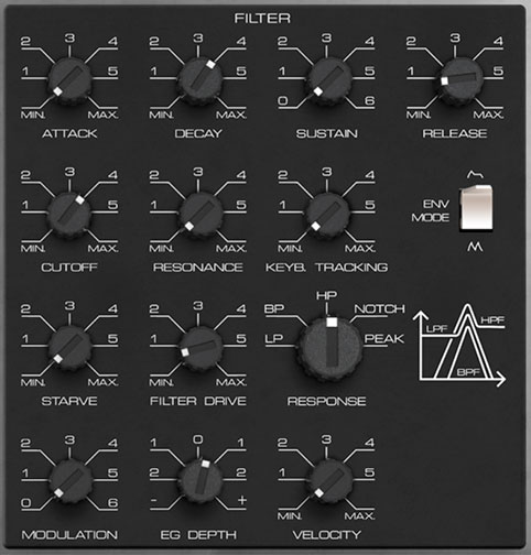
Filter Envelope Controls
The dedicated ADSR filter envelope controls are incorporated into the Filter section. The filter envelope is hardwired to filter cutoff frequency, with its depth controlled via the EG Depth knob. If you're not familiar with the operation of an ADSR envelope generator, please see How An ADSR Envelope Generator Works in the Amp section.
Attack- Defines the length of time for voltage to rise from minimum to maximum voltage when a key is played.
Decay- Defines the length of time for voltage to fall from the attack stage peak to sustain stage setting.
Sustain- Sets the voltage level following attack and decay phases while a note is held.
Release- Defines the length of time for voltage to fall from sustain level to minimum voltage when a key is released.
Cutoff- Sets the frequency where frequency attenuation begins. Its effect is dependent upon the currently selected filter Response setting.
Resonance- Emphasizes sound energy at and around the cutoff frequency by adding feedback from the filter's output back to its input. This is useful for creating commonly heard synth "wah" tones, especially when the cutoff frequency is modulated with an envelope generator or one of the LFO's.
Atomika's resonance circuit can result in some squelching and screaming at higher settings, so be cautious with volume when cranking the Resonance knob. That said, because of its propensity to distort, it usually doesn't get too crazy, because the distortion tends to act like a natural limiter. But hey, we gotta warn people, because who knows what folks will get up to (then blame us on momsbasementsynthdweller.com when everything goes awry because of the Resonance knob).
Keyboard Tracking- Causes the cutoff frequency to increase as ascending notes are played on the keyboard. The idea behind this that some (or all) of the keyboard CV signal is added to the cutoff frequency in order to offset the rising pitches of notes in order to maintain the brightness of notes as higher pitches are played. (If the filter cutoff frequency remained constant, lower notes would appear to sound brighter than higher ones.)
The original Polivoks did not include a keyboard tracking control - the tracking CV was "built-in" and set to a preset value. We decided to add the Keyboard Tracking control mainly to facilitate cranking the Resonance knob and "playing" the resulting pitched resonant notes across the keyboard.
Envelope Generator Mode- In the up position, the Filter envelope functions as a standard ADSR (attack/decay/sustain/release) envelope generator. In the down position, the Filter envelope is set to looping mode. This effectively converts the envelope generator to an LFO, with its controls affecting the modulation waveshape. The Attack and Decay controls are most effective here; be sure to set Sustain to a low value or the envelope won't loop at all.
Starve- This parameter is unique to the filter design, resulting from the aforementioned programmable-op-amp-incorrectly-used-as-filter architecture. If the settings are correct, the filter can take on an oscillating "bubbly" sound, for lack of better wording. Try Cutoff between 1 and 2, Resonance at max, and Starve between 5 and 6 as a starting point.
Filter Drive- This is not a standard filter overdrive/breakup control, but like Starve, is unique to how the Polivoks filter resonance circuit interacts with the power supply rails. The technical details aren't important; what you should know is that it tends to work best with Resonance at high settings, and the Filter Drive knob at very low or very high settings - all manner of radical distorted noises happen when Resonance is cranked and Filter Drive is set to 0!
Response- Selects the overall filter curves. The jaunty graphic to the right of the Response selector shows a rough visual approximation of the lowpass, bandpass, and highpass response curves, with vertical representing amplitude, and horizontal representing frequency.
LP (Lowpass)- Allows frequencies below the cutoff frequency to pass, but blocks frequencies above the cutoff frequency with an 12 dB/oct slope.
BP (Bandpass)- Allows a band of frequencies in the vicinity of the cutoff frequency to pass, with a 6 dB/oct slope on either side of the peak.
HP (Highpass)- Allows frequencies above the cutoff frequency to pass, but blocks frequencies below the cutoff frequency with a 12 dB/oct slope. Because they dramatically remove low frequencies, the highpass setting is useful for nasally tones with exaggerated high frequencies.
Notch- Removes a band of frequencies close to the cutoff frequency and allows all other frequencies to pass. The notch width varies dependent on the current Resonance setting, with low Resonance resulting in the widest Notch width. Notch filters are useful for pseudo-phaser effects when their cutoff frequency is swept, but hey, that's notch your problem, right? ("And the award for the most Daddest User Manual Joke goes to...")
Peak- A pronounced resonant peak at the cutoff frequency, and no rolloff on either side of the peak frequency. Incidentally, the Peak setting excels at really saturated, aggressive sounds when the Resonance knob is cranked.
By the way, similar to the one on the original instrument, that fanciful little graphic next to the Response control gives a rough visual indication of the lowpass, bandpass, and highpass filter behaviors. The vertical axis represents amplitude; the horizontal axis represents frequency.
Modulation- Sets the amount of mod depth from the Modulator section at top left. This is affected by the Mod Wheel switch in the Modulator section; for more info see the Modulator section.
EG Depth- Sets the amount of mod depth from the ADSR Filter envelope generator controls at the top of the filter section.
Velocity- Sets the how much the cutoff frequency is affected by keyboard velocity. To use the Velocity control, make sure the EG Depth knob is at a non-zero setting (we recommend starting full up). It works slightly "backwards" - increasing the the Velocity amount increases control range, so the cutoff frequency appears to decrease as the Velocity knob is increased.