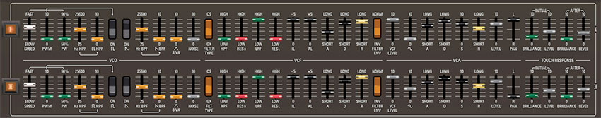
This is where the main synthesizer voicing controls are located. The architecture of the original CS-80 differs from typical analog synthesizers in that it contains two polyphonic "ranks," with each rank comprising a complete synthesizer voice consisting of a single oscillator, a highpass and lowpass filter, a noise generator, a sine wave oscillator, envelope generators for the filter and VCA respectively, and a VCA. These are referred to as rank I and II (these are Roman numerals). The Rank Voice Parameters section contains an identical sets of controls for each rank. A GX-80 sound consists of the two aforementioned I and II ranks when Global Controls Layer Mode is set to Single.
The Yamaha GX-1 featured four voice ranks instead of two, controlled either by one or two keyboards. The Layer Mode buttons let you select Single mode (two voice ranks - I/II, like a CS-80), Dual, or Split modes (four voice ranks - I/II/III/IV, like a GX-1). The Panel buttons select which voice parameters are currently displayed and controlled by the Rank Voice Parameter controls. The operation of the layer modes is fully explained in the Global Controls section.
GX-1 Controls
CS-80 and GX-1 voice architecture is very similar, but the GX-1 included some unique additional voicing controls, which we'll explain below. For the most part, GX-80's Rank Voice Parameter controls mimic the layout of the CS-80, but slider and switch controls found only on the GX-1 are orange in color for easy visual distinction.
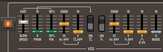
VCO Section
I/II/III/IV rank enable buttons- These enable and disable the ranks. When a rank is disabled, the rank's audio is muted and all associated controls are dimmed. If Layer Mode Dual or Split mode is currently active and Panel Lower is selected, the I and II rank indicators on the buttons will change to III and IV (as will all other I and II panel labels). The rank enable buttons are useful for soloing and muting ranks when editing sounds.
Speed- Sets the speed of the low-frequency oscillator that modulates pulse width (see next two controls).
PWM (Pulse Width Modulation)- Pulse-width modulation refers to modulating the width of a pulse wave using a low-frequency oscillator (LFO) - it's essentially the same as moving the slider back and forth. Note that each rank includes its own independent and asynchronous PWM LFO.
PW (Pulse Width)- Sets the width or "duty cycle" of pulse waves, from a perfect square (50%) to a very narrow pulse (90%) The PW controls have no effect on the sawtooth wave.
Highpass Filtered Pulse Wave- This is a unique Yamaha GX-1 feature. The pulse wave is split off and routed through a highpass resonator, thus removing low frequencies and greatly accentuating the selected frequency. This filter functions independently of the filters in the HPF and LPF sections, and its output is summed with the standard unfiltered pulse wave.
Hz HPF- Sets the pulse wave cutoff highpass filter cutoff frequency.
Pulse Wave HPF level- Sets the highpassed pulse wave level. This slider functions independent of the unfiltered pulse wave, and the pulse wave rocker switch has no effect on highpassed pulse wave output.
Pulse Wave on/off- Enables and disables the oscillator pulse wave. Note that it works "backwards" of most rocker switches, that is, the down position is on.
Sawtooth Wave on/off- Enables and disables the oscillator sawtooth wave. Note that it works "backwards" of most rocker switches, that is, the down position is on.
Bandpass Filtered Saw Wave- Also a GX-1 feature, this is very similar to the highpassed square wave, but here the saw wave is split off and routed through a bandpass resonator, which removes low and high frequencies, while letting the center "band" through, creating midrangey, resonant tones. This filter functions independently of the filters in the HPF and LPF sections, and its output is summed with the standard unfiltered saw wave.
Hz BPF- Sets the saw wave bandpass filter frequency.
Saw Wave BPF level- Sets the bandpassed saw wave level. This slider functions independently of the unfiltered saw wave, and the saw wave rocker switch has no effect on bandpassed saw wave output.
Triangle 8 VA- Sets the volume of a triangle wave, pitched one octave higher than the main oscillator waves. This is also a GX-1 feature.
Noise- Sets the level of white noise. White noise is a random signal in which all frequencies across the frequency spectrum are represented equally.
VCF Section
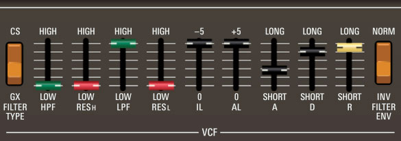
The CS-80 and GX-1 used completely different filter designs. The CS-80 uses a distortion-free 12 dB/oct filter topology while the GX-1 featured a unique 9 dB/oct design, which sounds buzzier and more open. Each voice rank includes cascaded independent highpass and lowpass filters. Combining both filters results in a bandpass response, which is excellent for brassy and stringy sounds, and at extreme settings, can create excessively thin and focused timbres.
Filter Type- Either filter style is independently selectable for each voice rank.
HPF frequency- Sets the cutoff frequency of the highpass filter - that is, all frequencies below the cutoff frequency are attenuated, reducing the overall amount of low frequency content.
Res H- Sets the amount of resonance for the highpass filter. Resonance emphasizes frequencies at or around the cutoff frequency. When combined with the filter envelope, it creates a typical synthesizer "wah" type sound.
LPF frequency- Sets the cutoff frequency of the lowpass filter - frequencies above the cutoff frequency are attenuated, reducing the overall amount of high frequency content.
Res L- Sets the amount of resonance of for the lowpass filter. Resonance emphasizes frequencies at or around the cutoff frequency. When combined with the filter envelope, it creates a typical synthesizer "wah" type sound.
VCF Envelope Controls
The GX-1 and CS-80 filter envelope control implementation is unusual; it's strongly advised that you read this section carefully.
First and foremost, the filter envelope does not include a sustain level control. Unlike other synth envelopes where the nominal envelope value is zero, the nominal level of the CS/GX filter envelope is whatever the filter cutoff slider is currently set to.
The envelope amount is affected by moving either or both IL and AL sliders from their zero settings. This moves the initial level (IL) down (more negative) and attack level (AL) up (more positive), thus making the overall envelope "bigger." IL defines the point at which the envelope starts and ends, ranging from 0 to -5V. AL defines the top of the envelope where attack switches to decay, ranging from 0 to +5V. Setting both IL and AL to 0 results in no filter envelope. The filter envelope "sustain level" is set using the HPF and LPF cutoff sliders.
The panel of the super-rare GX-1 programmer illustrates how the IL and AL sliders work together a little more clearly than the CS-80/GX-80, because the IL slider is positioned beneath the AL slider, and has a properly reversed travel. That is, its maximum setting of -5V is the slider's lowest position, and the IL and AL sliders "meet" in the middle at 0V, i.e. the current filter cutoff control setting. The diagram below is a recreation of the GX-1 programmer panel:
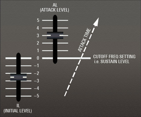
To achieve a typical attack/release envelope shape, where the envelope rises to the sustain level and then falls back when the key is released, raise the IL slider (more negative) and leave AL at zero. To get an attack/decay function, where the envelope rises and then falls back while the key is still down, raise the AL slider (more positive) and leave IL at zero. Other combinations of IL and AL settings will result in ADSR functions of different sizes.
It's important to remember that the filter envelope simultaneously modulates both highpass and lowpass cutoff frequencies. However, the envelope moves the HPF only half the amount (in octaves) compared to the LPF; this has two beneficial effects. First, it causes the bandpass to open up, and second, it prevents the HPF from completely removing all the beef from the sound. (If more low-frequency girth is desired, increase the sine wave slider in the VCA section - it's not affected by filter cutoff settings). The unique envelope movement of these filters is the trademark of these synths - don't be afraid of increasing HPF cutoff to achieve the "always bandpassing" signature tonality of the original instruments.
IL (Initial Level)- IL sets how far below the current cutoff frequency the envelope will begin when a key is played, and will end at when a key is released.
AL (Attack Level)- AL sets how far above the current cutoff frequency the envelope will climb when a key is played.
A (Attack)- Defines the length of time for cutoff frequency to rise from the IL setting to the AL setting when a key is played.
D (Decay)- Defines the length of time for cutoff frequency to fall from the attack stage peak (AL) to the current cutoff frequency setting.
R (Release)- Defines the length of time for cutoff frequency to fall back to the Initial Level when a key is released.
Invert Filter Envelope- When in the down Inv position, this reverses the effect the filter envelope has on cutoff frequencies. This is a GX-1 feature not found on the CS-80 (hence the orange switch).
"Always Be Bandpassing..."
An important thing to understand about the GX/CS voice architecture is that all filter modifiers, including the filter envelope generator, initial and after Brilliance, Sub Oscillator mod, built-in filter keyboard tracking, global Brilliance, and Keyboard Control Brilliance all affect the highpass filter AND lowpass filter cutoff frequencies simultaneously. This means that much of the time, the pulse and saw waves will be bandpass filtered to some degree, that is, high and low frequencies will be removed with "in-between" frequencies remaining intact. That said, the mod amount isn't the same - typically more mod signal is sent to the lowpass cutoff frequency than the highpass cutoff frequency.
This has two benefits. It allows the combined bandpass filter to open up and sound fuller, and it prevents the highpass filter from creeping up too high and destroying the low end. In fact, it's probably the defining characteristic of the CS sound, and certainly why these instruments are known for their punchy, brassy, midrange-y tone.
VCA Section
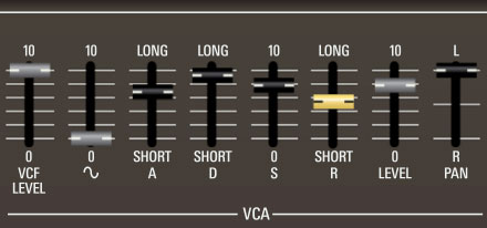
VCA stands for "voltage-controlled amplifier. Here you'll set incoming and outgoing volume, as well as amplitude envelope parameters.
VCF Level- Sets the input volume level from the preceding filter section.
Sine level- Sets the level of a sine wave oscillator at the same octave setting as the main oscillator. If you're wondering why this control isn't in the oscillator section, it's because a sine wave theoretically has no harmonics, so placing before the filter section would just reduce its volume. However, the original CS-80 sine wave isn't 100% pure - it has a few harmonics and has been reproduced accordingly.
The VCF Level and Sine level controls can be set to any balance; if you only want to hear the sine wave, simply set the VCF Level to zero.
A (Attack)- Defines the length of time for amplitude to rise from the IL setting to the AL setting when a key is played.
D (Decay)- Defines the length of time for amplitude to fall from the attack stage peak sustain level setting.
S (Sustain)- Sets the amplitude level following attack and decay phases while a note is held.
R (Release)- Defines the length of time for amplitude to fall to zero when a key is released.
Level- Sets the baseline level for volume dynamics (what you will hear with the lightest touch). If no dynamics are desired, set this control to full. If maximum dynamics are desired, set this control to zero and raise one or both of the other Level controls. See the Touch Response section below for more information.
Pan- Sets the rank position in the stereo field. The ability to pan the individual ranks was not available on the original hardware, and the results are spacious and wide, to say the least.
Touch Response
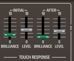
The Touch Response section allows polyphonic control of lowpass and highpass cutoff frequencies as well as amplitude via keyboard velocity and aftertouch.
There are 5 closely related controls on the right side of each rank that control keyboard dynamics. They are Level, Initial Level, After Level, Initial Brilliance, and After Brilliance. Although Level may at first glance appear to be a volume control for the rank, that is not really its purpose. Instead, volume should ideally be adjusted with VCF LEVEL and SINE LEVEL before the VCA ADSR Envelope.
The three Level controls adjust control voltages which go to a separate VCA which controls volume dynamics. The Level slider adjusts the VCA's starting level, Initial Level adjusts the velocity control voltage, and After Level adjusts the aftertouch control voltage. If no volume dynamics are desired, adjust Level all the way up. Bring in more dynamics by lowering Level while bringing up the Initial Level and/or After Level controls. To hear any output, at least one of the the Level controls needs to be turned up.
The Brilliance controls react similarly, though each filter's Cutoff control sets the filter's starting level.
The After/Brilliance and Level sliders work in conjunction with the Aftertouch Mode buttons to the left of the keyboard.
Initial- Sets how keyboard velocity (i.e. how hard a key is struck) affects filter frequency and VCA level.
Brilliance- Highpass and lowpass filter cutoff frequencies rise as keys are played harder. The higher the slider setting, the greater the effect. A setting of zero means velocity has no effect.
Level- VCA amplitude rises as keys are played harder. The higher the slider setting, the greater the effect. A setting of zero means velocity has no effect.
After- Sets how keyboard aftertouch (i.e. key pressure after the key is initially struck) affects filter frequency and VCA level.
Brilliance- Highpass and lowpass filter cutoff frequencies increase as keys are played harder. The higher the slider setting, the greater the effect. A setting of zero means velocity has no effect.
Level- VCA amplitude increases as keys are played harder. The higher the slider setting, the greater the effect. A setting of zero means velocity has no effect.