The Odyssey's filter section is a primary reason for its unique character, as well as a source of confusion for buyers new to the synth. That's because over the course of its lifetime, the Odyssey sported three different Voltage Controlled Filter (VCF) designs, resulting in three (sometimes radically) different tonalities.
Rather than making everyone argue over which one is best for which application, ODC 2800 includes all of them:
The first Odyssey (Model 2800), commonly called the Mk I, was built from (roughly) 1972 to 1975. These Odysseys are recognizable for their white front panels. The filter in the Mk I was called the 4023, and it was a 2-pole (12 dB/octave) state-variable filter – a type that became much more famous in 1975, when Tom Oberheim included his own version in the Synthesizer Expander Module (SEM). The 4023 is prized for its rough and raw character, with a lot of snarl and grit, although some users point out its noisier sound.
The Odyssey Mk II (Model 2810, with tweaked models up to 2815) was a transitional model in many ways. Over its product run, several important upgrades and new features were introduced that would come together in the Mk III – including two different filter designs. The VCF most closely associated with the black-and-gold Mk II was the 4035. This was a 4-pole (24 dB/octave) transistor ladder filter in the Moog style... in fact, a bit too much in the Moog style, as Moog politely informed ARP. The Moog ladder filter was patented, and ARP elected to avoid legal entanglements by changing the design. ODC 2800 lets you try this filter without having a lawyer on call; while it won't make the Odyssey sound like a Moog, it does have the solid low end and sweet resonance of a ladder filter, which pairs well with the ARP VCOs.
The final Odyssey, the Mk III (Model 2820, with variants up to 2823), was released in 1978 and built until the company folded in 1981. Perhaps the most familiar-looking Odyssey thanks to its striking black-and-orange color scheme, it used the filter that ARP created to replace the ladder design in the Mk II. This 4-pole filter, the 4075, was renowned for its highly stable behavior and exceptionally clean sound, with noise and distortion levels largely unheard of in synthesizers at the time.
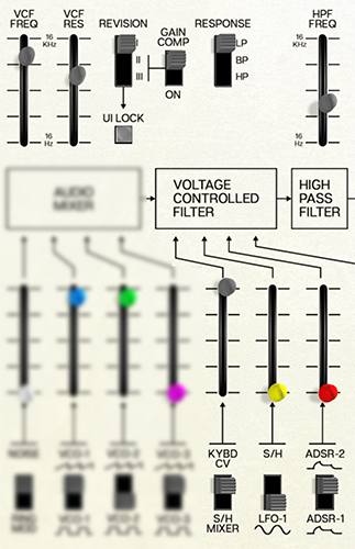
The main VCF controls are at the upper left.
VCF Freq- The cutoff frequency of the filter, ranging from 2 Hz to well over 20 kHz (the front panel markings are in honor of the original Odyssey, whose filter could be quite treble-deficient in some revisions).
VCF Res- The filter resonance, which will have a very different character with each filter type. In particular, the Mk I filter has a very "snarly" sound at very high resonances, vs. a sweeter resonant peak for the Mk II and Mk III.
Revision- This sets which of the three filter circuits (described above) is active. Click the switch to move back and forth between I, II, and III. At most filter settings, the tonal change will be instantly audible, particularly when jumping between the 2-pole Mk I and the 4-pole designs.
UI Lock- As a visual reference, when the Revision is changed, the front panel graphics all change to reflect the look of the three different Odyssey designs that used the three different filters. If you like a particular look because it's easier for you to read (or you just like the aesthetics), click UI Lock to keep it from changing when you change Revisions – or change patches to one with a different Revision.
Gain Comp- This switch compensates for the loss of gain at low frequencies that you'll hear in filters II and III when the resonance is cranked up. The original hardware has design limitations that result in this gain loss – the software lets you cheat a little and get it back.
Response- Oh, did we forget to mention that unlike the original Odyssey, ODC 2800 has a multimode filter? Oops, silly us. Click the switch to change the original lowpass design to a bandpass or highpass filter.
Modulation inputs- Below and to the right of the primary filter controls, there are four sliders to mix different control signals that modulate the cutoff frequency:
Input 1 is switchable between Keyboard CV and the Sample/Hold Mixer. Keyboard CV causes the filter cutoff to track the notes you play; when set to 100%, you can play the filter's resonant peak when it's cranked up to the point of self-oscillation, producing its own sine wave at the cutoff frequency.
Input 2 is switchable between the Sample/Hold and a sine wave from LFO 1.
Input 3 is switchable between the two ADSR Envelope Generators. Traditionally ADSR 2 is used to control filter cutoff, so it's the default setting.
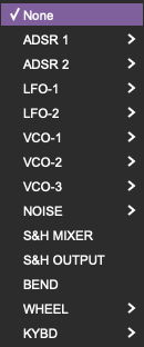
Input 4 is assignable to a variety of control signals. Click the Assign button to bring up the Modulation Source Menu, which is detailed in its own subsection of this User Guide:
HPF Freq- At the top right of the filter section, this slider controls the cutoff frequency of ODC 2800's highpass filter (HPF). This filter has a very gentle 1-pole (6 dB/octave) slope; it's non-resonant and can't be modulated directly (i.e., without assigning MIDI control). It can roll off excessive low end, turning the lowpass VCF into a sort of bandpass filter, or just tame unruly bass.
Having two filters in series was almost unheard of when it was introduced in the Odyssey, and was yet another way in which it stood out from the competition. This feature isn't discussed often, but it can be an unsung hero, either on the original Odyssey or in ODC 2800.
After passing through the two filters, the signal travels to the VCA for loudness control.