The original instrument made use of CEM3320 filter chips. These were very common in the heyday of polyphonic analog and hybrid synths, and were also used in the Prophet-5, Oberheim OB-Xa and OB-8, and many others. Unlike most other instruments that used the CEM chips in a basic 24 dB/oct lowpass configuration, the Elka used a multimode implementation that allowed selection of 24 dB/oct lowpass, 6 or 12 dB/oct bandpass, or 12 dB/oct highpass. This enabled many tonal colors that couldn't be achieved with typical analog polysynths.
About Filter Types
• A lowpass filter allows frequencies below the cutoff frequency setting to pass through, but blocks frequencies above the cutoff frequency.
• A highpass filter is the opposite of lowpass mode: high-frequency content remains, but low frequencies are removed as the cutoff frequency increases.
• Bandpass filters combine both lowpass and highpass modes, leaving sound only "in the middle" with amplitude falling off symmetrically on either side of the cutoff frequency.
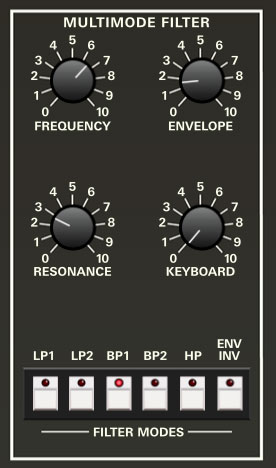
Controls
Frequency- Sets the frequency where frequency attenuation begins, i.e. which frequencies are allowed to pass, dependent on the current Filter Modes setting.
Envelope- The Envelope control applies modulation from the Filter Envelope to the cutoff frequency. This allows familiar auto filter sweeps. When raising the Envelope control, you'll generally want to lower the Cutoff control, as these controls sum.
Resonance- Resonance emphasizes sound energy at and around the current cutoff frequency by adding feedback from the filter's output back to its input. At lower settings, this can be used to create mild resonances such as those heard in acoustic instruments. At extreme settings, it can be used as a sine wave generator, but be careful as high resonance settings can result in loud, screamy, dog-spooking (and speaker blowing) occurrences.
Keyboard- This causes the cutoff frequency to increase as ascending notes are played on a keyboard. The idea behind this is that the Keyboard control applies a rising CV to the cutoff frequency in order to maintain the brightness of notes as higher pitches are played (because actual note frequencies rise as higher pitches are played).
Filter Modes- These select the overall filter behavior, as described in the About Filter Types section above, as follows:
LP1 (Lowpass)- Allows frequencies below the cutoff frequency to pass, but blocks frequencies above the cutoff frequency with a 24 dB/oct slope.
LP2 (Lowpass)- Allows frequencies below the cutoff frequency to pass, but blocks frequencies above the cutoff frequency with a 12 dB/oct slope. This has a slightly "sharper" sound than a 24 db/oct slope.
BP1 (Bandpass)- Allows a band of frequencies in the vicinity of the cutoff frequency to pass, with a 6 dB/oct slope.
BP2 (Bandpass)- Allows a band of frequencies in the vicinity of the cutoff frequency to pass, with a 12 dB/oct slope. This creates a narrower passband than BP1's 6 dB/oct slope, and a correspondingly sharper and thinner sound.
HP (Highpass)- Allows frequencies above the cutoff frequency to pass, but blocks frequencies below the cutoff frequency with a 12 dB/oct slope. Because they dramatically remove low frequencies, the highpass setting is useful for nasally tones with exaggerated high frequencies.
Envelope Invert- Though it's in the same group as the Filter Mode buttons, Envelope Invert is not a filter mode per se. When toggled, it reverses the polarity of the Filter Envelope's effect on the cutoff frequency (via the Envelope knob). Because the Filter Envelope works subtractively when the Envelope Invert button is engaged, it's most audible when the Frequency knob is at higher settings.
Filter Envelope
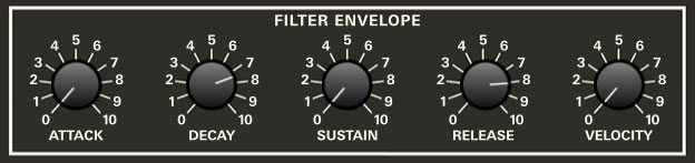
The Filter Envelope is a dedicated envelope generator for control of cutoff frequency (via the Envelope knob).
How An ADSR Envelope Generator Works
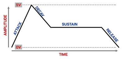
When Elka-X sees a gate voltage from a note, the envelope generator outputs a dynamically changing voltage, according to the settings of its four stages. The attack stage defines how long it takes for the output voltage to rise from zero to full scale. Once the attack stage reaches its max amount, it moves to the decay phase, which defines how long it takes to fall from full scale to the setting of the sustain phase. Unlike the attack, decay, and release phases, which define times, sustain simply sets the held voltage level following the attack and decay phases - this equates to the envelope output level while holding down a key. Finally, the release slider defines the the length of time it takes for the voltage to fall back to zero when the gate input voltage is removed, i.e. when the key is released.
Controls
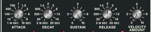
Attack- Defines the length of time for cutoff frequency voltage to rise from zero to full scale when a key is played.
Decay- Defines the length of time for cutoff frequency voltage to fall from the attack stage peak to sustain stage setting.
Sustain- Sets the cutoff frequency voltage level following attack and decay phases while a note is held.
Release- Defines the length of time for cutoff frequency voltage to fall from sustain level to zero when a key is released.
Velocity- Defines how much the envelope affects the filter cutoff frequency via keyboard velocity. When set to zero, keyboard velocity has no effect on cutoff frequency; all the way up results in maximum control range.