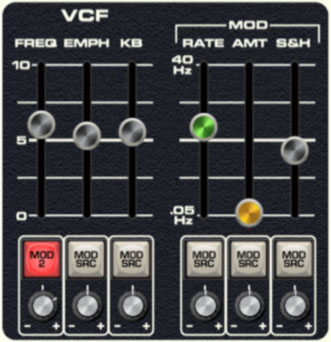
This is a standard 24db per/octave voltage-controlled lowpass filter along with a dedicated envelope generator for cutoff frequency control. Being a lowpass filter, it removes high frequencies as its cutoff frequency setting is decreased from max. Note that this is a single filter for all voices, sometimes referred to as a "paraphonic" implementation. This means that it's global for all notes, and the VCF envelope will retrigger any time a new note is played. This isn't so great for piano, clav, or other percussive sounds, but it's not too much of an issue for sustained pad, string, or organ-type sounds. The VCF and VCF Envelope controls are as follows:
Frequency - Sets the frequency where high-frequency attenuation begins.
A note about max cutoff frequency: If the cutoff frequency is open all the way, the sound still won't be at full brightness; in other words, some high frequencies are still attenuated. Full filter brightness can be achieved by using the VCF Envelope (detailed below), or by adding CV from the a mod source via the cutoff frequency Mod Src routing button and attenuator knob. This was done to accurately emulate the behavior of the real instrument's VCF (a lot of vintage analog synths have this behavior).
Emph (Resonance)- Emphasizes sound energy at and around the current cutoff frequency by adding feedback from the filter's output back to its input. Useful for typical synth "wah" sounds.
Mod - Rate/Amount - The VCF section includes an independent triangle-wave LFO that's hard-wired to frequency modulation. The Rate slider controls LFO speed, and the Amount slider controls LFO depth.
Mod - S&H (Sample and Hold) - Applies sample and hold (aka, random) modulation to the cutoff frequency. The sample and hold rate is controlled by the same clock as the triangle-wave LFO above, thus its rate is set with the same Rate control. The triangle-wave LFO and S&H can simultaneously modulate the cutoff frequency as desired.
Mod Source buttons and Attenuator knobs- The Mod Src selector buttons and attenuators beneath the sliders allow positive or inverted voltage control of the slider directly above. Clicking the Mod Src selector button opens a pop-up menu where the mod source can be selected. Once a mod source is chosen, the button turns red and its text changes to indicate the current mod source. To choose a different mod source, click the button and choose another modulator, or choose None to disable modulation. The attenuator knobs beneath the Mod Src buttons set a positive or inverted voltage control amount for the controls.
VCF Envelope
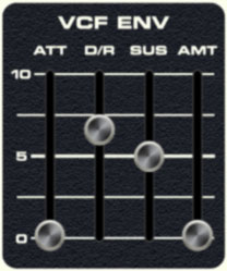
The VCF Envelope beneath the VCF section exclusively controls the VCF described above. Its controls are as follow:
Att (Attack)- Defines the length of time for VCF cutoff mod voltage to rise from minimum to maximum.
D/R (Decay/Release)- Defines the length of time for VCF cutoff mod voltage to fall from the Att stage peak to Sus stage setting (key held) or fall to zero (key released).
Sus (Sustain)- Sets the held VCF cutoff mod voltage following Att and D/R phases (key held).
Amt (Amount)- Defines the depth of envelope control of VCF cutoff. A setting of 0 has no effect on cutoff frequency; a setting of 10 would be maximum control.