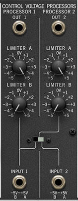
Like the many analog synthesizers, PS-3300 makes use of control voltages ranging from -5V ~ +5V. These voltages are used to control oscillator pitch and vibrato, filter cutoff, amp modulation and more. The Control Voltage Processors primary purpose is to control voltage ranges or "swing." (not the kind of swing heard in Bobby Brown songs in the late 80s).
PS-3300 includes two independent and identical CV processors.
Out 1/2 jacks- The output voltage of the Control Voltage Processor. If nothing is plugged in to the corresponding input jack below, the Out 1/ Out 2 jacks will produce a static voltage, adjustable between -5V to +5V. This has a number of uses, for example, it can be used to set oscillator pulse width to an exact amount by patching it to the Ext PWM Control jack and varying the PWM Intensity knob (make sure the PWM oscillator wave is selected).
Limiter A- Sets the uppermost voltage value. If the incoming voltage is positive, and Limiter A is set to a negative value, the voltage will be inverted (output will be a negative voltage).
Limiter B- Sets the lowest voltage value. If the incoming voltage is negative, and Limiter B is set to a positive value, the voltage will be inverted (output will be a positive voltage).
Routing switch- When switched to the left position, this mults Control Voltage Processor 1's input to Control Voltage Processor 2's input. If the switch is in the right position, both inputs and outputs are fully independent. Since PS-3300 allows unlimited multiple cables from any output jack, this switch is somewhat superfluous, but we included it for accuracy.
Input 1/2 jacks- Patch incoming control voltages here.
How the Control Voltage Processors Work
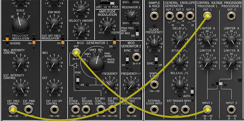
Since the Control Voltage Processors can initially be confusing, we're going to explain their functionality with an example - this will make them easy to grasp, we promise! Create the patch below as follows:

Click the New button at top left.
In the Signal Mixer section at the top of the Master Panel, set Ch-1 Volume to 0, and Ch-3 Volume to around 8.
(We're using Voice Panel 3 so our screen shots aren't crazy wide, but it doesn't matter which Voice Panel is used).Set Voice Panel 3 / Mod Generator 1 waveform to Rec. This gives us a perfect square modulation wave.
Patch a cable from Voice Panel 3 / Mod Generator 1 Out jack to Control Voltage Processor 1's Input 1 jack.
Patch another cable from Control Voltage Processor 1's Out 1 jack to Voice Panel 3 Ext Freq Control.
Turn the Ext Intensity Control knob all the way up. When a key is played, you should hear a six-octave wide trill. The LFO wave is alternating between -5V ~ +5V. Because PS-3300 uses the 1V/oct standard, this would correspond to ten octaves of pitch modulation (five octaves each direction). However, if you look closely at the panel beneath the Ext Freq Control jack, you'll see it's labeled -3V ~ +3V (the range is limited, because a 10-octave pitch mod range isn't musically that useful). The important point is that the LFO wave is alternating at its full range.
Try reducing the setting of Control Voltage Processor 1's Limiter A knob. The high pitch decreases as Limiter A's setting is reduced, because the high voltage is reduced.
Now reset the Limiter A knob to its max setting (+5V), and increase the setting of Control Voltage Processor 1's Limiter B knob. The low pitch increases as Limiter A's setting is reduced, because the low voltage is increased.
Setting both the Limiter A and Limiter B knobs to 0V "closes down" both sides of the swing to nothing - in fact, the same "cancellation" occurs when both knobs are in the same position, regardless of the the setting.
Up to this point, the Limiter A knob has always been at a higher setting than Limiter B. But what happens if Limiter B's setting is higher than Limiter A? The output becomes inverted - using our same square wave example, the "valley" (negative voltage) becomes high, and the peak (positive voltage) becomes low. This waveform inversion can be useful if you'd like the same modulation to affect sources conversely (pitch of one oscillator rises while the pitch of another oscillator falls, for example).
It should be clear that Limiter A and Limiter B's settings can be combined to limit voltages to any range. Note that the limiters will work on any kind of voltage input - including constantly changing sources, i.e. triangle and saw waves or even an envelope generator.
Here's one final Control Voltage Processor trick. If nothing is plugged into one an input jack, the output jack will output a static voltage from -5 ~ +5V, depending on the knob settings. This is useful for transposition, or for setting the Signal Generator PWM wave to an exact static (non-modulated) setting.