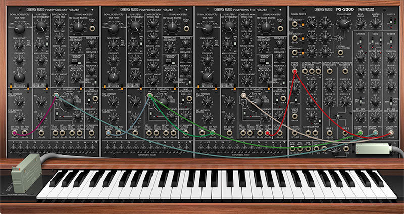
If you're not experienced with modular synthesis, the patch points may look a little intimidating, but we promise, they're not too hard to understand. And unlike a fully modular synth, PS-3300's semi-normalled connection scheme makes it easy to use only patching that you need, while leaving the rest of the instrument operating like a standard hard-wired synth.
Korg's PS-series instruments are quite possibly the only polyphonic synthesizers ever made incorporating modular synth-style patching. In some ways, this offered unheard of sonic flexibility for a polyphonic synthesis architecture. With that said, it's important to keep in mind that all of the patch cable modulation paths are strictly monophonic. That is, control signals are applied globally to all note pitches, filter cutoff frequency, etc. - there are no separate mod paths for individual note articulation. This naturally limits mod source and destination possibilities. If you're wondering why there isn't a particular mod routing, most likely, this is the reason. We didn't want to radically alter the design of the PS-3300, so we (mostly) stuck with the original design and intention.
(If you get into PS-3300's patching and find yourself wishing for full patching of all polyphonic control signals, let us recommend Cherry Audio's fabulous Voltage Modular platform, which includes a unique "poly cables" implementation.)
Semi-Normalled Connections
A self-contained, non-modular synthesizer, such as a Minimoog, is internally hard-wired. That is, the oscillators are permanently connected to the mixer inputs, the mixer outputs are connected to the filter inputs, and so on. A semi-normalled synth is similar, but there are jacks added to these connections throughout the instrument. With that in mind, semi-normalled is a short way of saying, "all sections are connected inside the synth, but plugging cables into the input jacks will interrupt internal connections and replace them with whatever is plugged into the jack." In the case of patch panel output jacks, plugging a cable in won't affect internal hard-wired connections, it just tacks on an additional output connection - this is known as "multing" from it.
CV Ins With Attenuators
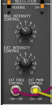
Many of PS-3300's CV input jacks are routed through attenuator knobs beneath the lower half of the voice panels prior to their destinations.
If you've patched a CV source to a CV input and nothing appears to be happening, check that the appropriate attenuator is turned up.
CV Ins Without Attenuators
Some of PS-3300's CV inputs have direct connections to their mod destinations, for example the External Attack Control and External Release Controls. Without an attenuator, the mod amount is always at "full blast." Depending on the situation, this usually isn't a problem - for example, if you're using a MIDI/USB controller's mod wheel to control a CV input, the mod wheel itself effectively becomes the attenuator.
CV Outs
Depending upon their function, CV outs can transmit various types of control signals. In most cases, they'll transmit a voltage ranging from either 0V ~ 5V (useful for oscillator pitch and amplitude control) or a range of -5V ~ 5V (useful for cyclical mod, such as vibrato or filter wahwah).
The tables below describe all patch panel ins and outs:
|
VOICE PANELS 1, 2, 3 |
|||
|---|---|---|---|
|
Name |
Input or Output* |
Function |
Attenuator Control |
|
EXT FREQ CONTROL |
INPUT |
pitch freq CV |
MG1 INTENSITY CONTROL |
|
EXT PWM CONTROL |
INPUT |
pulse width mod CV |
PWM INTENSITY |
|
EXT CUT OFF CONTROL |
INPUT |
LP filter freq mod CV |
EXT |
|
EXT ATTACK CONTROL |
INPUT |
attack time CV |
– |
|
EXT RELEASE CONTROL |
INPUT |
release time CV |
– |
|
EXT MG1 LEVEL CONTROL |
INPUT |
LFO 1 amount CV |
– |
|
EXT MG1 FREQ CONTROL |
INPUT |
LFO 1 rate CV |
– |
|
EXT RESONATOR FREQ CONTROL |
INPUT |
resonator 1, 2 ,3 freq CV |
RES INTENSITY |
|
MOD GENERATOR 1 OUT |
OUTPUT |
Mod Gen 1 CV output |
– |
|
MOD GENERATOR 2 OUT |
OUTPUT |
Mod Gen 2 CV output |
– |
|
SIGNAL MODIFIERS SIGNAL OUT |
OUTPUT |
Voice Panel audio output |
– |
|
MASTER PANEL |
|||
|---|---|---|---|
|
Name |
Input or Output* |
Function |
Attenuator Control |
|
SIGNAL MIXER EXT LEVEL CONTROL 1, 2, 3 |
INPUT |
indiv mixer channel level CV |
– |
|
SIGNAL MIXER EXT LEVEL CONTROL (master) |
INPUT |
master mixer level CV |
– |
|
SAMPLE & HOLD INPUT |
INPUT |
input to Sample & Hold |
– |
|
SAMPLE & HOLD OUTPUT |
OUTPUT |
output of Sample & Hold |
– |
|
GEN ENV GEN EXT TRIG INPUT 1 |
INPUT |
Gen Env Gen trigger input |
– |
|
GEN ENV GEN EXT TRIG INPUT 2 |
INPUT |
Gen Env Gen trigger input |
– |
|
GEN ENV GEN OUT 1 |
OUTPUT |
+5V ~ 0 env output |
– |
|
GEN ENV GEN OUT 2 |
OUTPUT |
-5 ~ +0V env output |
– |
|
GEN ENV GEN OUT 3 |
OUTPUT |
0 ~ +5V env output |
– |
|
CONTROL VOLTAGE PROCESSOR 1 OUT 1 |
OUTPUT |
CV Processor processed signal |
– |
|
CONTROL VOLTAGE PROCESSOR 2 OUT 2 |
OUTPUT |
CV Processor processed signal |
– |
|
CONTROL VOLTAGE PROCESSOR 1 INPUT 1 |
INPUT |
CV Processor input signal |
– |
|
CONTROL VOLTAGE PROCESSOR 2 INPUT 2 |
INPUT |
CV Processor input signal |
– |
|
PITCH BEND |
OUTPUT |
MIDI/USB pitch wheel CV |
– |
|
MOD WHEEL |
OUTPUT |
MIDI/USB mod wheel CV |
– |
|
KEYB VEL OUT |
OUTPUT |
MIDI/US keyb velocity CV |
– |
|
GATE OUT SINGLE |
OUTPUT |
MIDI/USB keyb switch single gate output |
– |
|
TRIG OUT MULTI |
OUTPUT |
MIDI/USB keyb switch multi trigger output |
– |
|
KBD GATE SELECT GATE OUT |
OUTPUT |
MIDI/USB keyb switch # of notes gate output |
– |
|
CHORUS EXT RATE CONTROL |
INPUT |
Chorus rate CV |
– |
|
ECHO EXT RATE CONTROL |
INPUT |
Echo rate CV |
– |
|
REVERB EXT MIX CONTROL |
INPUT |
Reverb Mix amount CV |
– |