Getting Started
PS-20 Primer
Top Toolbar, Preset, and Focus Control
VCO 1 and 2
Mixer
Highpass and Lowpass Filter
Modulation Generator
VCA
Envelope Generator 1 and 2
Voice Assigner and Pitch Settings
Output Section
Patch Panel Cables
Using The Patch Panel
Patch Panel Extras
External Signal Processor
Sequencer
Effects
MIDI Controllers Setup and The MIDI Tab
Using MPE
QWERTY Musical Typing Keyboard (MTK)
Settings
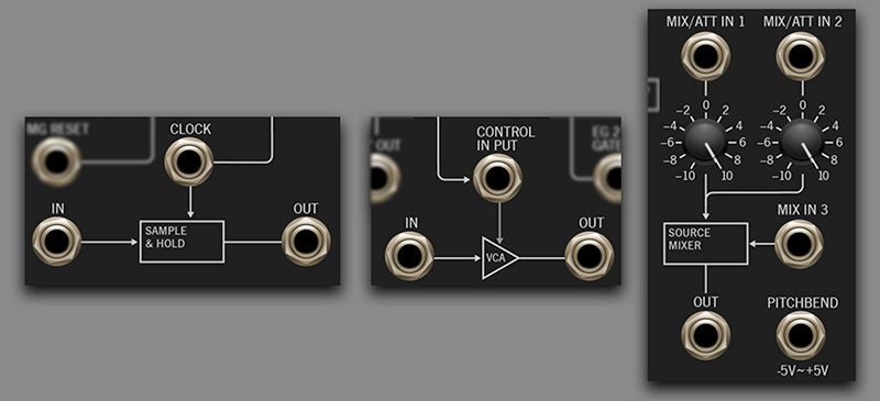
The patch panel primarily offers patch points for all standard synth components in the "knob" portion of PS-20's front panel. However, there are a three additional sections that are only accessible via patch cords in the patch panel section.
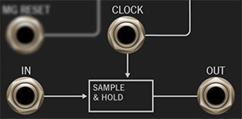
Sample & Hold
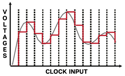
Below we've illustrated how a sample & hold works to make its operation easier to understand. In the image below, the smooth gray line shows a continuous input signal. Each time the module is triggered by an incoming clock signal, the current voltage is “sampled” and “held” until the next trigger. The red line shows the stepped output signal.
In- Patch incoming audio or control signals here.
Control Input- Patch a clock source here. By default, the Clock input is normalled from EG 1, but the connection can be overridden by patching any CV source to the Control Input jack. Typical clock sources would be the modulation generator, or one of the oscillators square or pulse wave outs.
Out- The "stepped" sample and hold output.
The most common use for a sample and hold is the familiar "random robot pitches" heard in a zillion sci-fi movies and 70s game shows (if you're old enough to remember Tic-Tac-Doe - how 'bout that Wink Martindale?!?). Requiring just two cables, this is a super easy patch to make with PS-20:
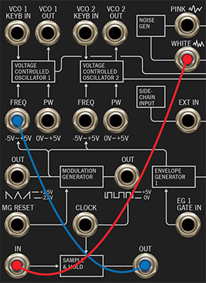
The White Noise output (red cable) provides our random voltage source, patched to the Sample & Hold In jack. The clock signal comes from the Modular Generator's pulse output, but no cable is needed because this is a normalled connection, as shown by the line to the Clock jack. The Sample & Hold output then feeds its stepped, random signal to VCO 1's Freq Input.
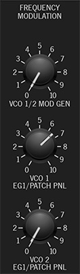
You'll need to turn up the VCO 1 EG1/Patch Panel attenuator in the Frequency Modulation section to hear the Sample & Hold modulation.
Keep in mind that the Sample & Hold has more uses than the just pitch mod. Random mod can also be applied to filter cutoff or VCA modulation. Crazy pseudo-sequencer effects can be achieved by feeding its input with slow-moving saw, ramp, or triangle waves (try VCO 2 in Lo mode) and modulating VCO 1's pitch.
Auxiliary VCA
The patch panel section also includes a "bonus" auxiliary VCA. Its main purpose on the original MS-20 was to allow modulation generator amount to be controlled via EG 1 or with a mod wheel. But with PS-20's additional patch panel I/O, it's possible to use the auxiliary VCA to create complex, "dual voice" patches, typically in conjunction with one more sequencer layers.
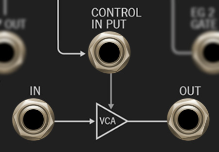
The auxiliary VCA works just like the main VCA described in the VCA manual section - it's essentially a volume knob, controlled by a CV.
In- Patch incoming audio or control signals here.
Control Input- Patch the CV to control level here. By default, the Control Input is normalled from EG 1, but the connection can be overridden by patching any CV source to the Control Input jack.
Out- The signal output.
Here's a patch that uses the mod wheel to control the amount of VCO vibrato:
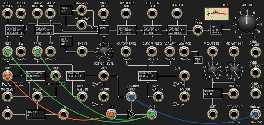
The Modulation Generator saw/triangle/ramp output is patched to the auxiliary VCA In (orange cable), and the auxiliary VCA Out is multed to both VCO 1 and VCO 2's Freq mod inputs. The Mod Wheel output jack is then patched to the auxiliary VCA Control input (blue cable). In this way, the mod wheel regulates the signal flowing through the VCA, i.e. the amount of signal traveling from the mod generator to the oscillator frequency mod inputs.
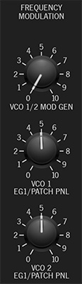
Don't forget to turn up the VCO 1 and VCO 2 EG1/Patch Panel attenuators in the Frequency Modulation section - these regulate the amount of signal received through the VCO Freq mod jacks.
Three-Input Source Mixer/Attenuator
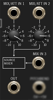
We've added a three-input mixer/attenuator/inverter that's really handy. It can be used for mixing audio or control signals, or as a simple attenuator if a single signal is routed through it.
Mix/Att In 1 and Mix/Att In 2 inputs and attenuators- The first two inputs include bipolar attenuators - that is, at center position, they pass no signal. Turning to the right passes positive signal; turning to the left passes inverted signal.
Mix In 3- This is a positive, unity-level input.
Out- The mixed output of all three signals.