Getting Started
PS-20 Primer
Top Toolbar, Preset, and Focus Control
VCO 1 and 2
Mixer
Highpass and Lowpass Filter
Modulation Generator
VCA
Envelope Generator 1 and 2
Voice Assigner and Pitch Settings
Output Section
Patch Panel Cables
Using The Patch Panel
Patch Panel Extras
External Signal Processor
Sequencer
Effects
MIDI Controllers Setup and The MIDI Tab
Using MPE
QWERTY Musical Typing Keyboard (MTK)
Settings
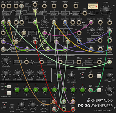
The Patch Panel may appear to be a terrifying mess of jacks, but we promise, it isn't too hard to understand, and unlike a fully modular synth, PS-20's semi-normalled connection scheme makes it easy to use only patching that you need, while leaving the rest of the instrument operating like a standard non-modular synth.
Semi-Normalled Connections
A self-contained, non-modular synthesizer, such as a Minimoog, is internally hard-wired. That is, the oscillators are permanently connected to the mixer inputs, the mixer outputs are connected to the filter inputs, and so on. A semi-normalled synth is similar, but there are jacks added to these connections throughout the instrument. With that in mind, semi-normalled is a short way of saying, "all sections are connected inside the synth, but plugging cables into the input jacks will interrupt internal connections and replace them with whatever is plugged into the jack." In the case of patch panel output jacks, plugging a cable in won't affect internal hard-wired connections, it just tacks on an additional output connection - this is known as "multing" from it.
Almost all of PS-20's input and output jacks are semi-normalled, and the panel names, dialog boxes, and arrows describe signal flow as well as their origin or destination in the circuit.
CV Ins Without Attenuators
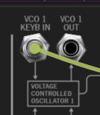
Some of PS-20's CV inputs have direct connections to their mod destinations. Let's look at the first jack connection at the top left, VCO Keyb In 1. When nothing is plugged into the jack, the keyboard pitch CV feeds into VCO 1, as shown by the arrow going to the Voltage Controlled Oscillator 1 box. If a cable is plugged into the jack, the keyboard pitch CV is disconnected and replaced by the cable plugged into this jack.
Because it is has no attenuator, the mod amount is always at "full blast." In the case of a keyboard CV input, this is what you'd usually want, to insure that the keyboard plays in 1/2 step semitones across its range. If you'd like to control the amount of CV, signals can be routed through the patch panel mixer/attenuator (beneath the VU meter).
CV Ins With Attenuators (Important, so read this)
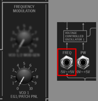
Many of PS-20's CV input jacks are routed to the front-panel attenuator knobs beneath the VCO's, mixer, VCF's, and Mod Generator prior to their destinations. All of the attenuator knobs do double-duty - if nothing is plugged into their corresponding mod jack inputs, they control the level of the hard-wired internal mod signal. The hard-wired mod signal is indicated in the attenuator name. For example, the above image shows the VCO1 EG1/ Patch Panel attenuator in the Frequency Modulation section. If nothing is plugged into Freq CV input, the attenuator controls the amount of frequency mod from EG1. When a cable is plugged into the Freq CV in jack, the internal EG1 routing is disconnected, and the attenuator controls the level of the cable plugged into the jack.
If you've patched a CV source to a CV input and nothing appears to be happening, check that the appropriate attenuator is turned up.
CV Outs
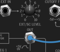
Now let's examine an output. Envelope Generator 1 is normally routed to VCO 1 and VCO 2 pitch (with its mod amount controlled by the VCO 1 EG1/Patch Panel and VCO 2 EG1/Patch Panel attenuators in the Frequency Modulation section beneath the Mixer). If a cable is plugged into the Envelope Generator 1 Out jack, its control signal can be routed to any other CV input. Unlike a CV input jack, CV outs are multed, so plugging a cable in has no effect EG1's hard-wired internal connections.
The table below describes all patch panel ins and outs. We've attempted to arrange the table in a sensible order, beginning with the VCO 1 connections at the top left.
|
NAME |
INPUT / OUTPUT |
FUNCTION |
NORMAL / ATTENUATOR |
|---|---|---|---|
|
VCO 1 / KEYB IN |
INPUT |
pitch freq CV |
– |
|
VCO 1 / OUT |
OUTPUT |
audio output |
– |
|
VCO 1 / FREQ |
INPUT |
freq mod CV |
FREQ MOD / VCO1 EG1/PATCH PANELPATCH PANEL |
|
VCO 1 / PW |
INPUT |
pulse width mod CV |
PWM / MOD GEN/PATCH PANEL |
|
VCO 2 / KEYB IN |
INPUT |
pitch freq CV |
– |
|
VCO 2 / OUT |
OUTPUT |
audio output |
– |
|
VCO 2 / FREQ |
INPUT |
freq mod CV |
FREQ MOD / VCO2 EG1/PATCH PANEL |
|
VCO 2 / PW |
INPUT |
pulse width mod CV |
PWM / MOD GEN/PATCH PANEL |
|
MIXER / WHITE NOISE |
OUTPUT |
white noise audio output |
– |
|
MIXER / PINK NOISE |
OUTPUT |
pink noise audio output |
– |
|
MIXER |
INPUT |
sidechain input/external input |
sidechain signal is normal |
|
MIXER / MIXER OUT |
OUTPUT |
mixer audio output |
– |
|
SIDECHAIN INPUT / EXT IN |
INPUT |
sidechain/external signal input |
– |
|
HP FILTER / HP FILTER OUT |
OUTPUT |
highpass filter audio out |
– |
|
HP FILTER / CUTOFF FREQ |
INPUT |
highpass filter cutoff mod |
CUTOFF FREQ MOD / EG2/PATCH PANEL |
|
LP FILTER / LP FILTER OUT |
OUTPUT |
lowpass filter audio out |
– |
|
LP FILTER / CUTOFF FREQ |
INPUT |
lowpass filter cutoff mod |
CUTOFF FREQ MOD / EG2/PATCH PANEL |
|
VCA / VCA OUT |
OUTPUT |
VCA audio output |
– |
|
VCA / VCA AMT |
INPUT |
VCA CV mod (all voices) |
– |
|
VCA / VCA MOD |
INPUT |
VCA CV mod (active voices only) |
VCA MODULATION / MOD GEN/PATCH PANEL |
|
PRE FX IN |
INPUT |
post VCA, pre FX audio input |
– |
|
MOD GENERATOR / SAW/TRI/RAMP OUT |
OUTPUT |
mod generator saw/triangle/ramp output |
– |
|
MOD GENERATOR / PULSE/SQUAR E OUT |
OUTPUT |
mod generator pulse/square output |
– |
|
MOD GENERATOR / MG RESET |
INPUT |
resets wave when gate or pulse is received |
– |
|
EG 1 / GATE IN |
INPUT |
envelope 1 gate input |
– |
|
EG 1 / OUT |
OUTPUT |
envelope 1 output |
– |
|
EG 1 / INV OUT |
OUTPUT |
envelope 1 output inverted |
– |
|
EG 2 / GATE IN |
INPUT |
envelope 2 gate input |
– |
|
EG 2 / OUT |
OUTPUT |
envelope 2 output |
– |
|
EG 2 / INV OUT |
OUTPUT |
envelope 2 output inverted |
– |
|
SAMPLE & HOLD / CLOCK |
INPUT |
clock input |
normalled from mod generator pulse out |
|
SAMPLE & HOLD / IN |
INPUT |
sample and hold input |
– |
|
SAMPLE & HOLD / OUT |
INPUT |
sample and hold output |
– |
|
AUX VCA / CONTROL INPUT |
INPUT |
aux VCA CV control input |
normalled from EG 1 output |
|
AUX VCA / IN |
INPUT |
aux VCA signal input |
– |
|
AUX VCA / OUT |
OUTPUT |
aux VCA signal output |
– |
|
PP MIXER / MIX/ATT IN 1 |
INPUT |
mixer signal input w/inverting atten knob |
– |
|
PP MIXER / MIX/ATT IN 2 |
INPUT |
mixer signal input w/inverting atten knob |
– |
|
PP MIXER / MIX/IN 3 |
INPUT |
mixer signal input |
– |
|
PP MIXER / OUT |
OUTPUT |
mixer signal output |
– |
|
CONTROLLER / KYBD CV OUT |
OUTPUT |
pitch CV from USB/MIDI controller |
– |
|
CONTROLLER / KYBD GATE OUT |
OUTPUT |
gate CV from USB/MIDI controller |
– |
|
CONTROLLER / KYBD VEL OUT |
OUTPUT |
velocity CV from USB/MIDI controller |
– |
|
CONTROLLER / PITCHBEND |
OUTPUT |
pitch bend CV from USB/MIDI controller |
– |
|
CONTROLLER / MOD WHL |
OUTPUT |
mod wheel CV from USB/MIDI controller |
– |