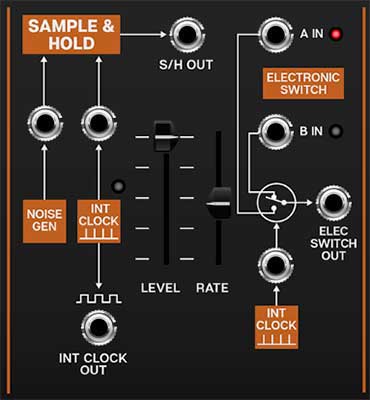
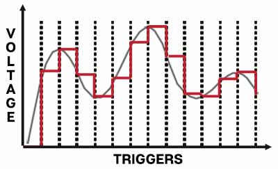
The sample and hold section repeatedly “samples” a varying input signal voltage, and outputs the "snapshot" voltage (i.e. a constant voltage) until it is triggered to sample again. Note that when we say "sample," we're referring to a simple incoming voltage - this isn't an audio sampler that you can sample and playback beats with. (Though this is the basic principle of how digital audio samplers operate).
Therefore a sample and hold has two inputs - the sample input, i.e. where it's grabbing the voltage samples from, and a clock input, which determines the duration between sample.
The Electronic Switch is alternates two input sources feeding a single output jack. By default, its normalled to the Sample & Hold clock, but it has a jack allowing switching from any CV source.
Sample & Hold
Sample Source (Noise Gen) input and jack- The noise generator is the default sample signal source. Because a noise source has all possible frequencies distributed in a random fashion, it makes an excellent source for "grabbing" completely random voltages. This signal can then be used to modulate oscillator pitch or filter frequency.
Alternate sample signals can be substituted by patching to the jack above the orange Noise Gen box. When modulating oscillator pitch, constantly moving low frequency waveforms such as triangle, sine, ramp, and saw work particularly well. Differing sample Rate slider and low-frequency oscillator rates yield endless melodic permutations.
Clock Source (Int Clock) input, jack, and rate LED- By default, the Sample & Hold uses its internal clock source to determine the rate at which the sample source is sampled. The LED above the orange box flashes to indicate the current clock rate.
Internal Clock Out jack- This output allows the Sample & Hold clock to be routed to any CA2600 input.
Level- Overall amount control for the S/H Out jack.
Rate- Sets the speed of the Sample & Hold's internal clock.
Sync button- Engaging the Sync button locks the Sample & Hold clock to master tempo. When engaged, the Rate slider snaps to note values ranging from 1/64th note triplet to 8 beats. Sync mode locks to the tempo in the top toolbar when using the CA2600 standalone version or the current project tempo when the plug-in version is used in a DAW.
Electronic Switch
The electronic switch alternates between two patched inputs sources at rate specified by the Sample & Hold clock or an alternate clock/switching source.
A and B input jacks and LEDs- These are the two inputs and can be CA2600 audio or control signals. The red and green LEDs will glow to show which input is currently active.
Clock Source (Int Clock) input and jack- By default, the Electronic Switch uses the Sample & Hold internal clock source to determine the rate at which the A and B inputs alternate. The Sample & Hold internal clock can be overridden by plugging any signal source into the jack above the Int Clock orange box. The Electronic Switch alternates any time it sees a 5V spike, so the "clock" source doesn't need to change at regular intervals - a keyboard gate signal could be used, for example.
Electronic Switch Out- Output jack for the alternating signal.