Voltage Controlled Oscillators
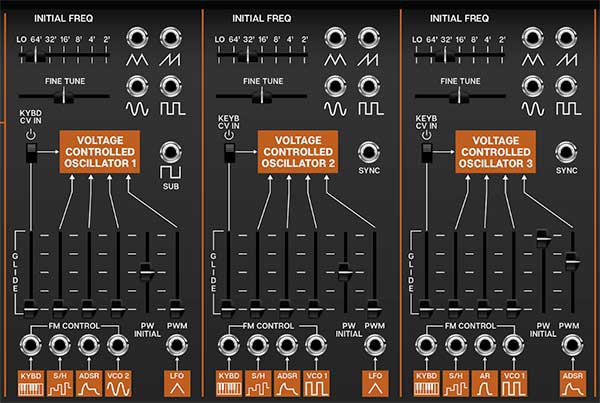
CA2600 includes three super-wide range oscillators that accurately model the imperfect waveforms of vintage ARP synthesizers. Unlike the original ARP 2600, all three have full functionality with all waveforms and pulse-width modulation capabilities. Their controls are almost identical, with a few sensible differences.
Initial Freq- Sets the basic pitch of the oscillator, displayed in traditional organ footage. Unlike the original ARP 2600, with its continuous pitch Initial Freq slider, CA2600 has stepped settings displayed in traditional organ octaves, making it much easier to tune to useful musical intervals. The Lo setting is beneath the audible range and is intended for use as a mod source.
Fine Tune- This can be used to fatten up two-oscillator patches by detuning a small amount, or for "building-in" a set interval. Its range is a smidge over a fifth, up or down.
Like a vintage ARP 2600, the oscillators do not have switches for wave selection. Instead, VCO 1's and 2's pulse wave and VCO 3's ramp wave are normalled to the Voltage Controlled Filter (VCF) audio inputs and gain sliders. To select a different oscillator wave, patch a cable from the appropriate VCO wave output jack to any of the VCF Audio input jacks to override the normalled routing.
Waveform output jacks- All three oscillators include triangle, ramp, sine, and pulse wave outputs; oscillator 1 adds a Sub out - this is a 50% square wave one octave below the Initial Freq setting. The Sub out is not affected by pulse width settings.
All oscillators have a ramp wave out, but no saw wave out (i.e. reverse ramp). There is no audible difference between ramp and saw waves if you're using the oscillators as audio sources, but you may want saw waves for "falling" mod effects when using the oscillators as low-frequency control sources. This can be accomplished by patching a ramp wave output to one of the inverters in the Voltage Processors section. (more on this in the, you guessed it, Voltage Processors section)
Sync (VCO 2 and VCO 3 only)- Feeding a wave or signal to this force resets the start of the waveform to the beginning of its cycle. Most often used to create the "tearing" sweep sounds made famous in The Cars' "Let's Go," by routing the output of another oscillator to the Hard Sync input and sweeping the pitch of the first oscillator.
Hard Sync is also useful when creating drum and percussion sounds to ensure that the wave starts precisely at the beginning of its cycle.
Keyb CV In- This switch connects or disconnects incoming MIDI pitch control. This defaults to on position, for standard keyboard (or sequencer) playing. Turning it off is useful for drones or sound effects when you don't want oscillator pitch to be affected by keyboard CV. Pitch can still be controlled with Initial Freq and Fine Tune controls as well as all FM Control CV inputs.
Glide- Also known as "portamento," glide delays the voltage change between pitches for a sliding effect. Though the Glide slider is situated above the normalled Pitch source and jack, it is not an attenuator for it, but it is in the signal path, so it will affect the normalled pitch CV or any signal plugged into the Kybd FM jack. CA2600 includes separate Glide controls for each oscillator - applying glide to only one oscillator is nice effect.
FM Control inputs and attenuators- These are the normalled and jack frequency modulation inputs for the oscillators. The slider control above each jack is an attenuator, affecting the amount of the normalled source, or if a cable is plugged into the jack, the amount of the signal from the patched source.
PW Initial- This sets the width or "duty-cycle" of the pulse wave. It has no effect on any other waveform. This defaults to 50%, i.e., a perfect square wave. Moving the slider up or down narrows its width as well as the thickness of sound until it almost disappears at its extremes.
PWM Control input and attenuator- Allows CV control of the pulse wave pulse width.
The table below shows the default sources and destinations for all three VCO's:
|
MOD SOURCE NAME |
NORMALLED SOURCE |
NORMALLED DESTINATION |
|---|---|---|
|
VCO 1/FM Control - Keyb CV |
incoming MIDI note data |
VCO 1 frequency (no atten slider) |
|
VCO 1/FM Control - S/H |
sample and hold output |
VCO 1 frequency |
|
VCO 1/FM Control - ADSR |
ADSR envelope output |
VCO 1 frequency |
|
VCO 1/FM Control - VCO 2 Sine |
VCO 2 sine wave output |
VCO 1 frequency |
|
VCO 1/PWM - LFO Triangle |
LFO triangle output |
VCO 1 pulse width |
|
VCO 2/FM Control - Keyb CV |
incoming MIDI note data |
VCO 2 frequency (no atten slider) |
|
VCO 2/FM Control - S/H |
sample and hold output |
VCO 2 frequency |
|
VCO 2/FM Control - AR |
AR envelope output |
VCO 2 frequency |
|
VCO 2/FM Control - VCO 1 Pulse |
VCO 1 pulse wave output |
VCO 2 frequency |
|
VCO 2/PWM - LFO Triangle |
LFO triangle output |
VCO 2 pulse width |
|
VCO 3/FM Control - Keyb CV |
incoming MIDI note data |
VCO 3 frequency (no atten slider) |
|
VCO 3/FM Control - S/H |
sample and hold output |
VCO 3 frequency |
|
VCO 3/FM Control - AR |
AR envelope output |
VCO 3 frequency |
|
VCO 3/FM Control - VCO 1 Pulse |
VCO 1 pulse wave output |
VCO 3 frequency |
|
VCO 3/PWM - ADSR |
ADSR envelope output |
VCO 3 pulse width |