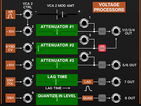
Voltage Processors
The Voltage Processors section is perhaps the most misunderstood section of the original ARP 2600, but it's actually easy to use, and very useful. It essentially consists of three invertible signal attenuators (the first one with an integrated VCA), a lag generator (aka, glide), and a 1/2 step voltage quantizer. As with other 2600 inputs, the input jacks include normalled signal paths for ease of use.
Since the horizontal sliders aren't labeled on the panel, we've Photoshopped in the green boxes and extra labels in the screenshot above to make it easier to understand the following descriptions:
Voltage Processor Attenuator 1/2 and VCA 2 (Input jacks #1 and #2)- This is a signal attenuator with an integrated VCA. If you're not familiar with attenuators, it's just a fancy word for "amount" control. The attenuator #1 slider acts as a static level control for signals plugged into the #2 jack. If the slider is set fully left, it's at zero; sliding to the right increases the amount. The level can be CV controlled if a cable is patched to the VCA 2 Ctrl input. The top VCA 2 Mod Amt slider determines the amount of CV controlling slider attenuator #1's amount. TheVCA 2 Mod Amt slider is bipolar; that is, it can reduce or increase the amount of of slider 2 depending on its position from the middle (and whether the incoming CV is positive or negative). The VCA 2 Mod Amt slider is at zero in center position.
To attenuate an external signal, override the normalled source by plugging a cable into the #2 jack. The attenuated output will be on the 1/2/3/4 Out jack. If nothing is plugged into the #2 input, a constant -10V signal is normalled to the #2 jack. This can be used to "bias" any CA2600 CV control input. The slider will control the voltage amount from zero, down to -10 volts.
Jack #1 directly feeds the 1/2/3/4 Out jack - it bypasses the attenuator #1 slider. This is useful if you want to invert a signal without altering its level. On the original 2600, this jack also acted as an additional mix input; but since you can stack as many inputs as you like on a single jack in CA2600, it's not really necessary.
Invert (Inv) button- This inverts the polarity of any signals traveling through, and has many uses. If the -10V source is being used, enabling the Inv button will make the voltage range 0 to +10V. The Inv button is also useful for "reversing" oscillators waveforms, particularly for transforming the ramp wave to a saw wave. All five voltage processor amount sliders include an invert button.
Voltage Processor Attenuator 2- Almost identical to attenuator #1, but the normalled source is the keyboard MIDI pitch CV. In conjunction with the Inv button, this can used to recreate the jazz legend Joe Zawinul's famous "reverse keyboard" trick (where low keys play highest notes and vice-versa). Simply hit attenuator #2's Inv button, then patch the 1/2/3/4 Out jack to the oscillator FM Control Kybd input jacks. The normalled input can be overridden by patching to jack #4. Jack #3 directly feeds the 1/2/3/4 Out jack - it bypasses the attenuator #2 slider.
Voltage Processor Attenuator 3- Attenuator #3 is also almost identical to attenuator #1, but the normalled constant voltage source is +10V instead of -10V (but it can be changed to -10V by engaging the Inv button). The normalled input can be overridden by patching to jack #6. Jack #5 directly feeds the 5/6 Out jack - it bypasses the attenuator #3 slider.
Voltage Processor Lag Time (Lag)- The Lag Time slider looks like the others, but it's not - it's not an attenuator, it's a lag (aka glide or slew) generator. Lag generators are most commonly used to create sliding effects by slowing down the stepped changes in pitch from a keyboard, but they're useful for other things, such as smoothing the changing the stepped voltages from random/sample & hold voltages.
Note that CA2600 has an individual lag generator built into each oscillator, so you won't need to use the Voltage Processors lag generator for keyboard glide.
Voltage Processor Quantize In Level (Quantizer)- Control voltages fed through the quantizer voltage processor will be rounded to the nearest 1/12V step, i.e., the nearest half-step. This is useful for transforming constantly changing (ramp, saw, triangle, or sine waves) or randomly stepped (sample & hold) waves into musically useful melodies. Note that quantizing occurs after the attenuator slider, so adjusting it alters the amount of signal going to the quantizer, which effectively changes the pitch range.
In order to properly hear 1/2 step pitches, make sure to set the mod destination attenuator (usually one of the oscillator FM Control inputs) all they way up. Use the horizontal slider and the speed of whatever you're feeding into the quantizer to fine-tune the note range and speed.
Since we love making tables, here's one illustrating all inputs, outputs, and processing of the Voltage Processors section:
|
SLIDER |
NORMALLED SOURCE |
SECONDARY INPUT? |
OUTPUT JACK |
|---|---|---|---|
|
VCA 2 Mod Amount |
VCA 2 CTRL jack only |
N/A |
N/A |
|
Attenuator #1 |
-10 volt source |
yes |
1/2/3/4 Out |
|
Attenuator #2 |
keyboard pitch CV |
yes |
1/2/3/4 Out |
|
Attenuator #3 |
+10 volt source |
yes |
5/6 Out |
|
Lag Time |
envelope follower output |
no |
7 Out |
|
Quantize Input Level |
sample & hold output |
no |
8 Out |