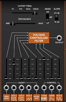
Voltage Controlled Filter
CA2600's filter section models the early ladder-style filter used in early ARP synthesizers, but unlike the original ARP 2600, It can be switched between lowpass, bandpass, and highpass modes, with 12- or 24-db per octave slopes.
If you're not familiar with how filters work, a lowpass filter allows frequencies below the cutoff frequency setting to pass through, but blocks frequencies above the cutoff frequency. A highpass filter does opposite: it allows frequencies above the cutoff frequency setting to pass through, but blocks frequencies below the cutoff frequency. In practice, this means a lowpass filter is useful for removing high frequencies, and a highpass filter is useful for removing low frequencies. A bandpass filter combines both lowpass and highpass filters thus allowing the "in-between" frequencies to pass.
Modulating cutoff frequencies via envelope generators, low-frequency oscillators, and more opens the door to endless tone colors.
Cutoff Freq- Sets the frequency where attenuation begins. Attenuation occurs above (Iowpass mode) or below the cutoff frequency (highpass mode). In the case of a bandpass filter, the cutoff setting determines a center freq with a band of frequencies above and below passing through.
Resonance- Emphasizes sound energy at and around the current cutoff frequency by adding feedback from the filter's output back to its input. At lower settings, this can be used to create mild resonances such as those heard in acoustic instruments. At more extreme settings, resonance can create a pure sine wave at its own frequency (you can adjust its pitch with the Cutoff knob). Be careful with this knob as it can get loud at extreme settings.
Mode- Selects highpass, bandpass, or lowpass modes (as described above).
Slope- The nature of how a filter works is that frequencies "fall off" above or below the cutoff frequency. Slope adjusts the steepness of this slope. Set to lowpass mode, a 12db per/octave filter has a shallower slope, whereas a 24db per/octave filter has a steeper slope (as well as more pronounced character with the resonance knob turned up).
Output jack- The direct audio out of the VCF section, routable to any CA2600 input..
Audio inputs and attenuators- These are the filter's audio inputs; these effectively act as a mixer for all audio sources routed through the filter. When the input jacks are used, any CA2600 audio output can be routed through the filter. Although there are "only" five jack inputs, CA-2600's unlimited mult jacks allow an unlimited number of sources to be routed to the filter.
The slider control above each jack is an attenuator, affecting the amount of the normalled source, or if a cable is plugged into the jack, the amount of the signal from the patched source.
Control inputs and attenuators- These are the frequency modulation inputs, affecting cutoff frequency. Because these work additively with the Cutoff Freq slider setting, it's generally a good idea to turn down the initial Cutoff Freq setting when using mod sources. The slider control above each jack is an attenuator, affecting the amount of the normalled source, or if a cable is plugged into the jack, the amount of the signal from the patched source.
When the Resonance control is toward max, the filter will "ring"- used in conjunction with the Keyb Control slider, this allows the filter to act as an additional sine wave oscillator. It's particularly effective when carefully mixed with the noise generator for half-noise/half-tonal "snowflake" tones.
The table below shows the filter's default sources and destinations.
|
MOD SOURCE/AUDIO INPUT NAME |
NORMALLED SOURCE |
NORMALLED DESTINATION |
|---|---|---|
|
VCF/Audio Input - Ring Mod |
ring mod output |
VCF audio input |
|
VCF/Audio Input - VCO 1 Pulse |
VCO 1 pulse wave output |
VCF audio input |
|
VCF/Audio Input - VCO 2 Pulse |
VCO 2 pulse wave output |
VCF audio input |
|
VCF/Audio Input - VCO 3 Ramp |
VCO 3 ramp wave output |
VCF audio input |
|
VCF/Audio Input - Noise |
noise generator output |
VCF audio input |
|
VCF/Control - Keyb CV |
incoming MIDI note data |
VCF cutoff frequency |
|
VCF/Control - ADSR |
ADSR envelope output |
VCF cutoff frequency |
|
VCF/Control - VCO 2 sine |
VCO 2 sine wave output |
VCF cutoff frequency |