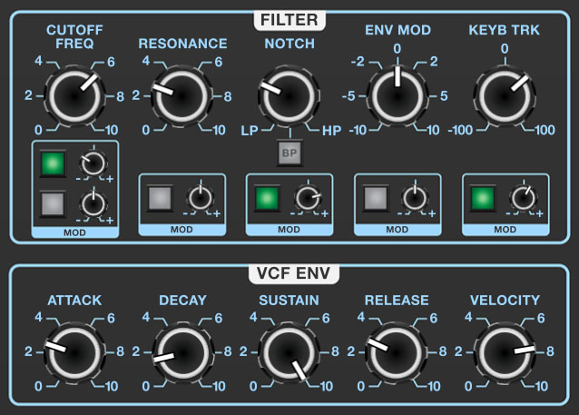
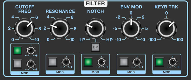
Dreamsynth uses a 12 dB/oct state-variable filter. "State-variable" refers to its curves - its Notch knob lets you choose lowpass, highpass or anywhere in between. The BP button bypasses the Notch knob and enables bandpass mode. The 12 dB/oct curve gives it a brighter overall tonality than a typical ladder filter, which works well with Dreamsynth's many brighter, bell-like digital waves.
If you're not familiar with how filters work, a lowpass filter allows frequencies below the cutoff frequency setting to pass through, but blocks frequencies above the cutoff frequency. Highpass is the opposite of lowpass mode: high-frequency content remains, but low frequencies are removed as the cutoff frequency increases. The BP button enables bandpass mode, combining both lowpass and highpass modes, leaving sound only "in the middle." The cutoff frequency lies roughly halfway between the falloff on each side. Setting the LP>HP/Notch knob to its center position (BP button disabled) results in a notch response - this is the opposite of bandpass, i.e. a small band of the frequency spectrum is removed but all frequencies above and below pass through. This may not sound very useful, but sweeping the frequency of a notch filter results in an interesting phaser-like sound.
Frequency- Sets the frequency where frequency attenuation begins. Its effect is dependent upon the currently chosen filter mode (lowpass, highpass, bandpass, or notch).
Cutoff Frequency and Mod boxes- Sets the frequency where frequency attenuation begins with its effect dependent upon the currently chosen lowpass/bandpass/notch/highpass/etc. filter mode. The modulation controls beneath allow CV control of the cutoff frequency; two identical sets of mod controls are provided allowing two independent cutoff mod sources.
Resonance- Emphasizes sound energy at and around the cutoff frequency by adding feedback from the filter's output back to its input. This is useful for creating commonly heard synth "wah" tones, especially when the cutoff frequency is modulated with an envelope generator or one of the LFO's.
Resonance and Mod box- Emphasizes sound energy at and around the cutoff frequency by adding feedback from the filter's output back to its input. This is useful for creating commonly heard synth "wah" tones, especially when the cutoff frequency is modulated. The modulation controls beneath allow CV control of the resonance
LP>HP/Notch control, BP button, and Mod box- The Notch knob continuously varies the filter response from lowpass to highpass as the knob is rotated from left to right. The middle position creates a notch response. Clicking the BP button puts the filter in bandpass mode and disables the LP>HP/Notch knob - the knob and its markings will dim when the BP switch is engaged. The modulation controls beneath allow CV control of the LP>HP/Notch knob.
BP (bandpass) switch- Alters the filter response to bandpass when engaged (i.e. combination of lowpass and highpass leaving frequencies "in the middle." The LP>HP knob disappears when the BP switch is enabled.
Envelope Mod and Mod box- Sets the amount of modulation from the VCF Env section beneath. Turn clockwise from center for positive modulation, or counterclockwise from center for inverted modulation. The modulation controls beneath allow CV control of the amount of envelope mod.
Keyboard Track and Mod box- This causes the cutoff frequency to increase as ascending notes are played on the keyboard. The idea behind this is, because actual note frequencies rise as higher pitches are played, the KB Track control applies a rising CV to the cutoff frequency in order to maintain the brightness of notes as higher pitches are played. Turn clockwise from center for positive modulation (filter gets brighter as higher notes are played), or counterclockwise from center for inverted modulation (filter gets duller as notes higher notes are played). The modulation controls beneath allow CV control of the amount of keyboard tracking.
Filter Envelope Generator
The filter section includes a dedicated envelope generator for control of cutoff frequency (via the Envelope Mod knob). Here's an overview of how an ADSR envelope generator works:
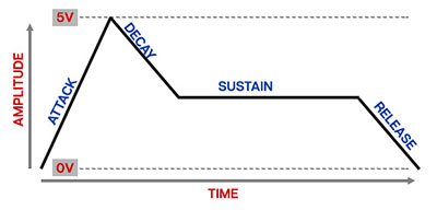
When Dreamsynth sees a gate voltage from a note, the envelope generator outputs a dynamically changing voltage, according to the settings of its four stages. The attack stage defines how long it takes for the output voltage to rise from 0 to 5 volts. Once the attack stage reaches 5V, it moves to the decay phase, which defines how long it takes to fall from 5V to the setting of the sustain phase. Unlike the attack, decay, and release phases, which define times, sustain simply sets the held voltage level following the attack and decay phases - this equates to the envelope output level while holding down a key. Finally, the release slider defines the length of time it takes for the voltage to fall back to 0V when the gate input voltage is removed, i.e. when the key is released.
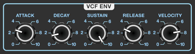
Attack- Defines the length of time for voltage to rise from 0V to 5V when a key is played.
Decay- Defines the length of time for voltage to fall from the attack stage 5V peak to sustain stage setting.
Sustain- Sets the voltage level following attack and decay phases while a note is held.
Release- Defines the length of time for voltage to fall from sustain level to 0V when a key is released.
Velocity- Defines how much the envelope affects the filter cutoff frequency via keyboard velocity. When set to zero, keyboard velocity has no effect on cutoff frequency; all the way up results in maximum control range.