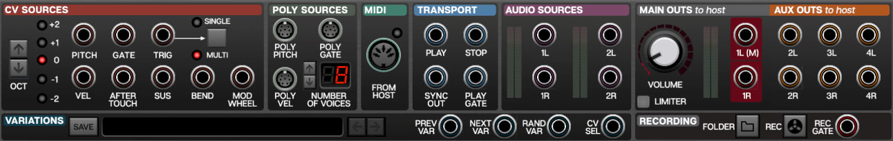
The input/output, aka I/O Panel, is Voltage’s "mission control." Here you’ll route audio signals, virtual control voltages, and MIDI to and from your computer, audio hardware, and DAW software. It's also where the powerful patch Variations section and inbuilt WAV Recording section live.
The standard round “mini” jacks send or receive virtual control voltages or "CV" just like a hardware modular synthesizer. These conform to the 1V/octave standard used in most analog synthesizers and can only transmit a single signal at any time. The Poly Sources section contains “poly jacks,” capable of transmitting up to 16 simultaneous signals; the five-pin jack in the MIDI section can transmit up to 16 channels of note and controller data, just like its hardware counterpart.
CV Sources
Oct- Transposes the pitch of the outgoing pitch control voltage in octaves.The LEDs to the right display the transposition interval.
Pitch- This is the pitch control voltage output. This usually is patched to an oscillator keyboard CV input, allowing oscillator pitch to track the keyboard in chromatic half-steps.
Gate- Outputs a constant 5V gate signal for as long as a key is pressed. This typically is patched to an envelope generator or voltage-controlled amplifier to control amplitude.
Trig- A trigger signal is much like a gate signal, but instead of staying high while a key is held, it briefly outputs 5V then returns to 0V (roughly 0.02 milliseconds). It’s often used to turn something on or off, or trigger a "one-shot" drum sound.
Single/Multi- Defines how the Gate and Trigger voltages behave when a key is struck while another key is held. In Single mode, a new gate and trigger voltage will not be sent until all previously held keys are released. In Multi mode, new gate and trigger voltages are sent any time a new key is played. (Because the gate voltage is already "high," it will very briefly dip to zero volts when a new key is struck in order to let the module know to retrigger.)
Vel- Outputs a velocity control voltage between 0V and 5V, proportionate to how hard the key (or pad) is struck when using a velocity-sensitive controller.
Aftertouch- Outputs a control voltage between 0V and 5V, proportionate to ongoing key pressure when using a controller that transmits aftertouch.
Sus- Outputs a 5V control voltage when a MIDI sustain pedal message greater than 64 is received.
Bend- Outputs a control voltage between -5V and 5V, proportionate to pitch wheel movements. No voltage is transmitted at nominal position.
Mod Wheel- Outputs a control voltage between 0V and 5V, proportionate to mod wheel position.
Poly Sources
These are a special type of jack, capable of transmitting up to sixteen separate "lanes" of CV's, for use with special poly modules from Cherry Audio, PSP, and others. Poly modules and cables make creating and playing poly patches a cinch!
They make use of a special "poly" cable, identifiable by its slight larger D-shaped connector and striped cables. Poly cables can only be patched to an appropriate poly jack. In addition to poly oscillators, filters, amps, mixers, etc., Voltage Modular includes a number of utility modules for splitting and converting poly cable signals to standard "mono" CV's for tremendous flexibility (type "poly" in the Library search field to see them).
Poly Pitch- This transmits pitch control voltages.
Poly Gate- Outputs 5V gate signals for as long as keys are pressed.
Poly Vel- Outputs control voltages between 0V and 5V, proportionate to how hard the key (or pad) is struck when a velocity-sensitive controller is used.
Number of Voices- Globally sets the maximum number of poly voices, up to 16 voices. Reducing the number of voices may be helpful if you're using a computer with limited CPU.
MIDI
Voltage Modular’s MIDI From Host jack transmits polyphonic pitch, note on-off, and MIDI CC data from external keyboard controllers and other devices. When used with various MIDI-compatible modules, this allows for polyphonic patches, arpeggios and more. Voltage MIDI cables are a little fatter than "standard" patch cables and can only be routed to modules with MIDI jacks, including the Poly Oscillator, Arpeggiator, MIDI File Player, and a number of MIDI modules. The LED beside the jack indicates when MIDI data is being received from a controller.
Transport
Sorry, this isn’t some nifty Star Trek doodad, but it’s still pretty cool. The transport section carries 5V trigger CVs that simplify using and syncing Voltage in DAW projects or in the standalone version of Voltage.
Play- Transmits a 5V trigger when play mode is initiated in DAW host software.
Stop- Transmits a 5V trigger when stop mode is initiated in DAW host software.
Sync Out- Transmits a constant 96-pulse-per-quarter-note (PPQN) signal used to synchronize sequencers and other modules to DAW host tempo. These are intended for use with Voltage’s Sync Divider module, which essentially "slow down" the super-fast sync signal to musically relevant note clock values.
The standalone version of Voltage will output 96 PPQN sync at the tempo specified in the Tempo field of the top tool bar. The Tempo field does not appear in the plug-in instrument versions, because the sync signal is derived from DAW project settings.
There are a couple of important things to understand about sync signals:
Sync signals are dumb: Sync signals have no idea where the "one" is, or whether your DAW is playing or stopped. If a sync signal is routed to the Sync Divider module and its clock is sent to a sequencer, the sequencer will play at the same tempo as the host DAW project, but “shifted” in time by some random (and usually undesirable) amount which will likely make you insane. Please don’t hop on a forum and tell the world that Voltage won’t play in time. Instead, keep reading…
Use the Reset jack for perfect timing: You’ll notice that the Sync Divider, all sequencer modules, and most other timing/trigger-related modules have Reset input jacks. Routing the Transport section Play CV out to these resets these modules to "one" the instant the DAW play button is pressed, forcing everybody to play in time together. (Make sure the DAW play marker is starting on an even beat when you hit play, or else everything in Voltage will play in perfect time, but out of time with the DAW project.)
Play Gate- Outputs a constant 5V signal any time the DAW host is in play mode. This isn’t necessary to play sequenced patches in sync, but it can be handy for more esoteric applications, such as opening voltage-controlled amplifiers during playback.
Audio Sources
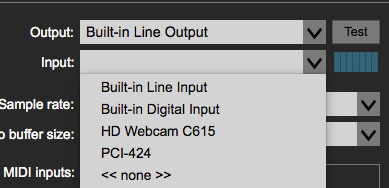
These allow audio to be routed in from either a host DAW when using the Voltage plug-in version (via the plug-in’s sidechain inputs) or via the computer’s onboard audio inputs when using the Voltage standalone edition. The Audio In sources can be configured in Settings (gear icon in the top toolbar) when using the standalone version.
and selecting the Input pop-up window. Input level can be set using the horizontal meter next to the pop-up, or with the input meters by the jacks in the I/O Panel.
The Audio Sources are useful when using Voltage as an insert effect in a DAW (check out the Insert & Bus Effects category in the presets). They can also be used as carrier and modulator sources with the super cool Vocoder module.
Main Outs To Host
This is Voltage’s master output section.
Volume Knob- Voltage Modular’s master volume. Note that like the CV Octave and Single/Multi settings, its setting is stored with patches.
Limiter- Clicking this engages a transparent-sounding audio level limiter across the final output bus. Its intention is to prevent blowing your head off with loud or obnoxious patches. Safety first at Cherry Audio!
Main Outs To Host 1L(M)/1R jacks- The main out jacks that the final module of a patch is plugged into- the final module must be plugged into these or the neighboring Aux Outs in order to hear sound ("Hello, tech support? It doesn’t make any noise…").
Are They Inputs or Outputs? The concept can be a little confusing: these jacks are routed to your computer’s audio hardware. Technically, they’re inputs, because you’re plugging an output of a module into them, but since they’re internally attached to your computer’s audio hardware, we call them "outputs." (Incidentally, we had some "spirited discourses" on this topic and how to name them appropriately. Just plug the final module in here and everything will be fine, we promise.)
Aux Outs To Host
These work like the Main Outs To Host jacks explained in the preceding paragraph, but they’re routed to your DAW or audio hardware additional outputs. Depending on the audio interface used, they can potentially be custom routed within a DAW’s virtual mixer or set up to output to additional DAW audio buses or audio interface physical outputs. A useful application would be to route a patch containing multiple drum modules through different DAW plug-in effects. (Kick to a compressor, snare to a reverb, etc.)
Variations
The Variations panel allows saving of all knob, slider, switch, or other control settings for individual patches. Variations only store control positions - they do not store patch cable routings. The concept of Variations is to treat a given patch as its own instrument, with variations representing different control settings on that instrument, much like a standard hard-wired synth with presets.
Save button- Click the Save button, enter a name in the dialog box, and click OK. You can save as many variations as you like.
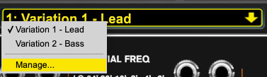
Forward/Back arrow buttons- Used to select the previous or next variation. Variations may also be selected by clicking the downward arrow at the right of the display and selecting the desired variation.
Variations CV Jacks
These allow the use of CV’s to select variations in a couple different ways.
Prev Var- Decrements the variation selection back when a voltage > than 2.5V is received.
Next Var- Increments the variation selection forward when a voltage > than 2.5V is received.
Rand Var- Randomly selects a new variation when a voltage > than 2.5V is received.
CV Sel- Allows selection of any current variation with a voltage input between 0 and 5V. The total number of variations is divided evenly over the 0-5V span. For example, if there were two variations, variation 1 would be selected from 0-2.49V, and variation 2 would be selected if the voltage was 2.5-5V. This is particularly useful if you’re using a sequencer to select variations.
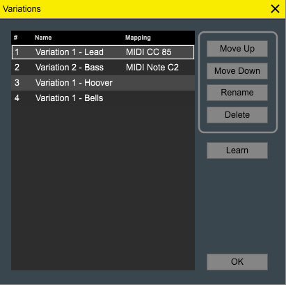
Variations Management
The Variation Management window allows renaming, deleting, and changing the order of Variations. It also lets you assign any MIDI controller to select a specific variation, which opens a lot of creative possibilities. To open the Variations Management window, click on a variation name in the display and select Manage…
Move Up/Move Down- These buttons change the order of the Variations list. This can be important if the variations are intended to play chronologically in a performance situation. To edit the order, click on a variation name, then click the Move Up or Move Down button until the variation is in the desired location.
Rename- Click this to open an edit field and rename the currently selected variation. Variations may also be renamed by double-clicking their name in the list.
Delete- Clears the selected variation. You’ll get an, “Are you sure?” prompt, but deletion can’t undone, so be careful.
Learn- Allows assignment of any MIDI controller to select a variation. Select the variation you’d like to assign, click the Learn button to arm learn mode and move the external control you’d like to select the current variation. Any type of controller can be assigned, including continuous controls such as knobs and sliders, but momentary buttons, drum pads, or keyboard keys make the most sense.
All of the above functions can also be performed by right-clicking a variation in the list. MIDI controller assignments can also be unlearned by right-clicking.
When you’re done editing variations, click the OK button.
Recording
The Recording section is a fast and easy to use WAV recorder. It can used in the plug-in or standalone versions, but it’s especially useful when using the standalone version. Recordings will be 48 kHz/32-bit WAV files.
Folder- Opens a file browser where the default destination of recorded files can be set. Voltage remembers this location, so you won’t need to set it every time.
Rec- Click to start recording. The button will glow red during recording. Click again to stop recording… easy-peasy. A separate new file is created each time recording is initiated.
Recordings are sourced from the Main Outs To Host jacks only- the Aux Outs jacks do not feed into the recorder. Appropriate levels should be set using the meters in the Main Outs To Host section prior to recording. The Main Outs section Limiter is not in the recording path.
Rec Gate- Engages recording when a constant CV > 2.5V is applied. Recording continues as long as the gate CV is high, and stops when the CV is removed (specifically, if the gate CV is < 2.5V). A new recording file is created when the CV goes high; in other words, engaging and disengaging recording with the Rec Gate input creates new files each time the CV goes high and low.
The Rec Gate input is not intended for use with trigger signals; a trigger signal would just create a very short recording.
Cable Normalization
Strictly speaking, this is module-specific feature, but because it involves the I/O Panel, we'll discuss it here.
Voltage modules can be coded to communicate directly with I/O Panel connections without the use of patch cords via “invisible” patch cords. The idea is to speed up setup by automatically configuring often-used cables and routings.
For example, the Cherry Audio DCO-60 and Synth Voice voice modules use normalized connections to connect I/O Panel Pitch and Gate CV outputs to the appropriate oscillator and envelope generator inputs. This eliminates the need for cabling, and makes setting up these "full voice" modules exceptionally easy. Dependent upon how a particular module is programmed, any I/O Panel input or output jack of any type can be normalized to any input or output of that module.
Cable normalization does not strictly apply to I/O Panel connections; connections within a module may be normalized as well. With its numerous normalized modulation input jacks, our Synth Voice module showcases this design approach particularly well.
One thing to be aware with normalized connections is that input jacks behave a little differently than outputs. If an output jack is normalized to a connection, and a cable is plugged into that output, the normalized connection is not affected; it simply treats any extra cables as if it were a multed output. Conversely, if a cable is plugged into a normalized input, the "invisible" normalled connection is broken and removed from the signal path.