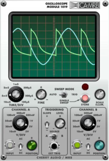
The Cherry Audio / MRB VM2500 module 1019 Oscilloscope is a versatile dual-trace scope modeled after analog units of the 1970s. The 1019 is one of several modules ARP planned to add to the 2500 line, but unfortunately never did. There is no detailed description of what this scope might have been like, so this is our take on it, and it's likely far better than what was planned. The 1019 has features found on high-end scopes such as AC/DC coupled inputs, calibrated sweep and vertical amplifiers, single-sweep mode, and variable level triggering from either of the two input channels or an external source.
Inputs and Controls
Time/Div- Controls the horizontal sweep speed of the trace. As the knob is turned clockwise, the sweep speed increases and the waveform display spreads out (i.e., zooms). The dial markings, in milliseconds (mS) and microseconds (uS), indicate how much time it takes for the sweep to pass one square (division) of the grid. Because it is calibrated, the period and frequency of waveforms can be determined by noting how much time the displayed cycles take.
Example: If the dial is set to 1mS and the waveform takes four divisions to complete a cycle, that means one cycle takes four milliseconds (0.004sec). Using the reciprocal (1/0.004), the frequency of the waveform can be determined: 250Hz. Oscilloscopes can measure frequencies this way when frequency counters have an impossible time with complicated waveforms.
Fine- Provides fine adjustment of the sweep speed. Keep this control at 0 to retain the Time/Div calibration (if you care).
Sweep Mode- Determines how horizontal sweeps are initiated. In Auto mode, the sweep is in "free run" mode, with the next sweep starting immediately after the last one finishes. Single Sweep allows single events to be captured by pressing the Store button. When pressed, one sweep will occur and freeze. The LED illuminates to indicate that this is a stored, frozen waveform. Trig (probably the most frequently used mode) utilizes the Triggering controls in the center and enables stabilization of complex waveforms.
Scale Illum.- Changes the "backlighting" of the grid.
Channel A/Channel B- These are the vertical amplifiers for the two traces. Channel A controls the green trace; Channel B controls the blue trace. Having two different colored traces is not "70s-correct," but we thought everyone would go crazy deciphering two green traces like an old CRT scope.
V/Div (Volts per Division)- Controls the vertical sensitivity. The dial markings indicate how many volts occupy one vertical square.
Input- Patch input signals here.
AC/DC- In the AC position, this switch allows you to remove any DC offset from the input signal by passing it through a 1Hz highpass filter. The result will always be a vertically centered waveform. In the DC position, the signal passes through unchanged. This control has no effect on the world's most famous mediocre rock band.
Position- Moves the trace up and down. This is very handy for separating the two traces on the screen for easier viewing and comparison. It can also be used to line up features of the wave on the grid for simplified voltage measurements.
Triggering- When Sweep Mode is set to Trig, these controls are used to adjust the sweep triggering to create a stable display. The idea is to start the sweep at the same point in the waveform every time - this way, the waveform doesn't jump all over the place from one sweep to the next.
Slope- Determines which direction the waveform has to be traveling to initiate a trigger (i.e., up or down).
Level- Controls the voltage threshold at which triggering occurs. For example, when viewing a sawtooth wave running through a highly resonant filter (i.e., a very complex waveform), the Level control can be set to trigger at the very top of the highest peak. By picking out this unique feature of the wave, the sweep always triggers at this spot, resulting in a stable display. If Trig mode is currently enabled and no waveform is visible, this means triggering has not occurred - this can be corrected by adjusting the Level control.
Source- Selects triggering from the signal in Channel A or Channel B, or from an external source. Sometimes when looking at complex signals, a simpler signal can be tapped elsewhere in the patch for use as a trigger - this is where Ext Trig comes in handy.