The ring modulator was invented by Frank A. Cowan in 1934 and patented in 1935 as an improvement on the invention of Clyde R. Keith at Bell Labs. The original application was in the field of analogue telephony for frequency-division multiplexing for carrying multiple voice signals over telephone cables. We're not totally sure what that means either, and if it sounds like we cut-and-pasted that blurb from Wikipedia, it's because we did. Anyway, ring modulators (also known as a "balanced modulators") date back to the earliest days of electronic music, and were one of the handful of ways audio signals could be radically manipulated back in the pre-synthesizer days of musique concrète, which is French for "bunch-of-weird-French-dudes-making-a-racket-with-tape-recorders-and-test-oscillators."
When two audio sources are inputted, the output contains only the sum and difference frequencies of the two signals, while removing common frequencies. The audio result is useful for creating sounds with inharmonic frequency content, which is useful for synthesizing bell and metallic sounds.
In order to facilitate processing a single input signal, ring modulators often include an onboard oscillator. VM Rackmode Ring Modulator's oscillator is not unlike a typical analog synthesizer oscillator, featuring range controls, and multiple waveforms. Its pitch can also be "played" using Voltage Modular CV signals, allowing for (somewhat) more musical exploits in the realm of ring mod madness.
Input Section
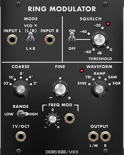
A ring modulator needs two input signals to do its magic; the Mode selector defines how the signals are combined.
Input L/R- This is where input signals are patched. These can be a standard stereo audio signal or two completely different mono signals.
Input Mode Switch-
VCO x (L/R)- Combines the onboard Voltage-Controlled Oscillator (VCO) with incoming left/right signal.
L x R- Combines the left and right signals of an incoming stereo audio signal. The Ring Modulator will have no affect on mono signals in L x R mode.
Squelch Section
Squelch Threshold and lamp- Allows fine-tuning of input level to prevent bleedthrough of the unprocessed signal to the processed signal. Thanks to the wonder of modern computers, bleedthrough is a far less of a concern than with analog hardware frequency shifters, but it's included to accurately replicate the original.
Turning the knob clockwise sets the input threshold higher until the input signal completely disappears. The lamp illuminates to indicate signal is passing.
Squelch Switch- Say that three times fast... enables and disables Squelch.
Voltage-Controlled Oscillator Section
The Voltage-Controlled Oscillator (VCO) signal is combined with the incoming audio signals when the Input Mode Switch is set to the VCO x (L/R) position.
Coarse- Sets the the VCO's overall coarse pitch range in standard organ footage settings of 32', 16', 8', 4', and 2'.
Fine- Allows fine-tuning of pitch by 1.25 octaves, up or down.
Waveform- Selects the VCO audio waveform. Available waveforms are sine, triangle, ramp, saw, and square. The LED flashes at the current frequency rate.
Freq Mod CV jack and attenuator- Sets the modulation depth applied to VCO pitch. Center position equals no modulation; turning clockwise applies positive mod, turning counterclockwise applies negative mod.
1V/Oct jack- Allows oscillator pitch control in standard semi-tones via CV.
Output jacks- The ring modulated output signal(s).