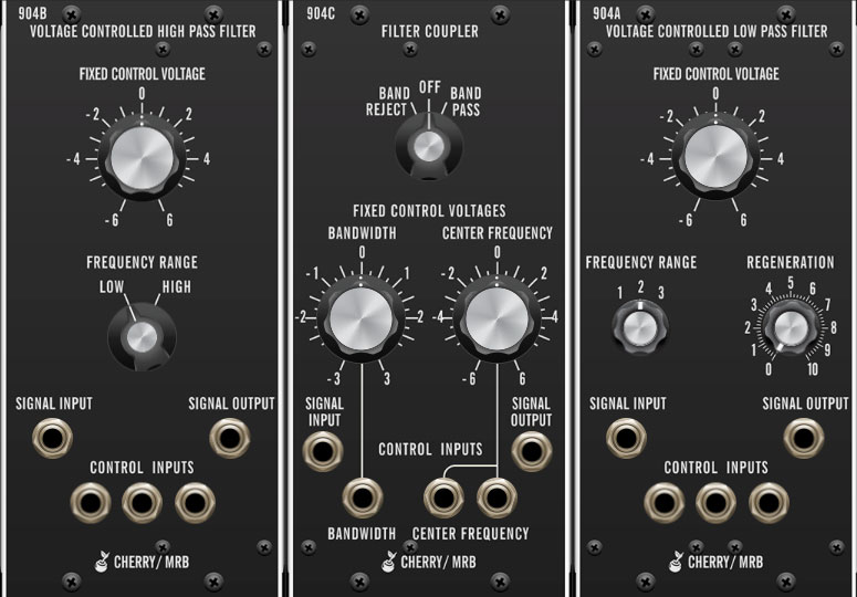
The 904A and 904B modules are emulations of the classic transistor ladder-style low pass and high pass filters, respectively. There are three separate modules: 904A is the classic 24dB/oct, low pass filter, 904B is a 24dB/oct high pass filter, and the 904C Filter Coupler allows 904A and 904B to be combined for band reject and band pass responses.
Following is an explanation of how each filter type works:
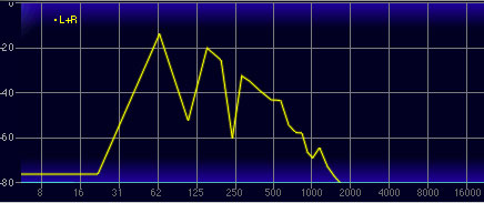
A low pass filter allows frequencies below the cutoff frequency setting to pass through, but blocks frequencies above the cutoff frequency. The frequency plot above shows the effect of a low pass filter with its cutoff set at 412 Hz on a sawtooth wave. (The vertical axis represents amplitude and the horizontal axis represents frequency.) You can see how the high-frequency content trails off as it gets higher.
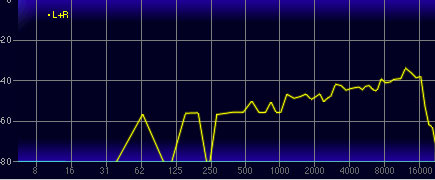
This plot shows the same oscillator signal and cutoff frequency setting using the high pass mode. This is the opposite of low pass mode: high-frequency content remains, but low frequencies are removed as the cutoff frequency increases.
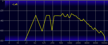
The plot above shows the same oscillator signal and cutoff frequency using a band pass filter. Band pass mode combines both low pass and high pass modes, leaving sound only "in the middle," aka the pass band... which should not be confused with The Gap Band, who will let frequencies across the audio spectrum pass through, and drop the bomb on you, baby.
A band reject filter is the inverse of band pass filter: a small spectrum of frequencies between the low pass and high pass settings are eliminated. This may not seem useful, but when the cutoff frequencies are modulated, band reject filters (also known as "notch" filters) can be used to create nifty sweeping phaser-like sounds ("phasers" as in the guitar stomp box effect, not the gun Capt. Kirk stunned green aliens with).
Module Configurations
The 904 modules are unique in that they can be used independently or in conjunction. As such we've provided a couple different versions - the 904A Low Pass and 904B High Pass filters are provided as individual modules, as well as together with the 904C Filter Coupler as one large module. In this configuration, the low pass and high pass filters are internally connected to the 904C Coupler, allowing band reject and band pass responses. The 904C Filter Coupler doesn't process sound on its own; in the original hardware modular system, it is internally connected to the 904A and 904B modules. Because of this, 904C isn't provided as a single module.
Inputs, Outputs, and Controls
904A Voltage Controlled Low Pass Filter
Fixed Control Voltage- Sets the frequency where high-frequency attenuation begins, over a 12-octave range. This control is generally called "cutoff frequency" on just about every other synth on the planet (remember that these designs date from the mid-60s). Turning to the left "closes" the filter for darker tone, and turning to the right "opens" it for brighter tone.
Frequency Range- Shifts the overall range of the Fixed Control Voltage knob in two-octave increments.
Regeneration- Also known as resonance or "Q," regeneration emphasizes sound energy at and around the current cutoff frequency by adding feedback from the filter's output back to its input. At lower settings, this can be used to create mild resonances such as those heard in acoustic instruments. At more extreme settings, resonance can create a pure sine wave at its own frequency (variable via the Fixed Control Voltage knob). Be careful with this knob as it can get loud at extreme settings.
Signal Input jack- Patch audio signals in here.
Control Inputs jacks- CV mod inputs. These sum with the Fixed Control Voltage frequency.
Signal Output jack- The filter output signal.
904B Voltage Controlled High Pass Filter
Fixed Control Voltage- Sets the frequency where low-frequency attenuation begins, over a 12-octave range. This control is generally called "cutoff frequency" on just about every other synth on the planet. Turning to the left lets more low/fundamental frequencies pass through, and turning to the right attenuates low frequencies.
Frequency Range- Shifts the overall range of the Fixed Control Voltage knob in 1.25 octave increments.
Signal Input jack- Patch audio signals in here.
Control Inputs jacks- CV mod inputs. These sum with the Fixed Control Voltage frequency.
Signal Output jack- The filter output signal.
904C Filter Coupler
As mentioned above, the 904C Filter Coupler internally connects the 904A Low Pass and 904B High Pass filter to enable band reject and band pass responses. Signals can be patched directly to and from the coupler module when using band reject and band pass modes.
Band Reject/Off/Band Pass switch- Selects the overall filter response behavior. In the Off position, the low pass and high pass filters are effectively disconnected and function as normal; their respective panel signal input and output jacks can be used for signal routing.
When set to the Band Pass position, the low pass and high pass filters are connected in series; i.e. the low pass filter removes high frequencies, and the high pass filter simultaneously removes low frequencies, allowing the "in-between" frequencies to pass.
The Band Reject setting is the inverse of the Band Pass setting - the central frequencies between the low pass filters are removed.
Bandwidth- Sets the frequency span of the pass band up to three octaves.
Center Frequency- Sets the central frequency.
For correct Filter Coupler control behavior, the 904A Low Pass and 904B High Pass Fixed Control Voltage and Frequency Range controls should all be set to center position.
Setting the 904A and 904B controls differently won't hurt anything, but the coupler controls may not behave as expected.
Signal Input jack- Patch audio signals in here.
Bandwidth jack- CV mod input affecting bandwidth.
Control Inputs jacks- CV mod inputs. These sum with the Center Frequency.
Signal Output jack- The filter output signal.