The VM911 Envelope Generator module is a standard "ADSR"-style envelope generator, with slightly unconventional control names. Remember that this modules was originally developed in the mid-60s, before analog synthesis terminology was cemented.
If you're not familiar with the operation of envelope generators, here's an overview:
When a gate voltage is sent to the Gate jack, the envelope generator outputs a voltage that changes dynamically according to the settings of its four stages.
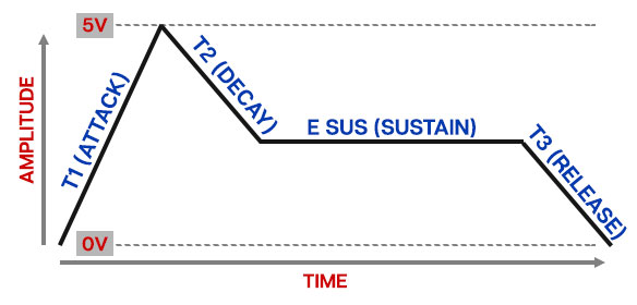
The T1 (attack) stage defines how long it takes for the output voltage to rise from 0 to 5 volts. Once the attack stage reaches 5V, it moves to the T2 (decay) phase, which defines how long it takes to fall from 5V to the setting of the E Sus (sustain) phase. Unlike the T1, T2, and T3 phases, each of which define a time, E Sus simply sets the held voltage level following the T1 and T2 phases - this usually equates to the envelope output level while holding down a key on a keyboard controller. Finally, the T3 knob defines the the length of time it takes for the voltage to fall back to 0V when the gate input voltage is removed (typically when you let go of a key on a keyboard controller).
For those interested, the T1 is (almost) linear, and T2 and T3 curve logarithmically.
(BTW, Esus is so named because E is the symbol for voltage in electro-speak. Make sure to spout this kind of knowledge at social gatherings - we guarantee you'll be the hit of the party.)
V-Triggers vs. S-Triggers
If you haven't used actual vintage modular synthesizers, you can probably skip this section with no life-altering consequences. If you're a cork-sniffin', vintage analog aficionado, this section is ALL you.
V-triggers and S-triggers refer to two types of signal used to activate envelope generators. The most common type is a V-trigger, more commonly referred to as a "gate" signal. This is usually a +5V DC signal. As long as the the gate voltage is high, the envelope generator runs through its attack and decay phases, then holds at the sustain voltage until the gate goes to zero (typically this occurs when a key is released), at which point the envelope moves to the release stage.
For most triggering applications, the original instruments used S-triggers, short for "shorting" triggers. This was a simple switch circuit where shorting the two conductors triggered envelopes; the envelope would run through its stages as above as long as the conductors were shorted. When the the conductors were disconnected, the envelope would move to the release stage. The thinking was was that any switch could be used to trigger the envelopes - footswitches, toggles, etc.
Ultimately, S-triggers proved to be the Betamax of envelope triggering methods - just about every modern synth uses gate signals. Additionally, in order to avoid operational calamity, S-triggers used a non-standard, two-blade "Cinch-Jones" connector, further complicating things.
Though we strove for accuracy in every aspect of these modules, to put it bluntly, we saw no benefit in recreating S-triggers within the confines of the Voltage Modular environment. The end result would have no impact on response or sound quality - it would've just complicated interfacing with other modules. With that in mind, the Cherry Audio/MRB VM900 modules all make use of standard gate voltages and "normal" Voltage Modular cables for triggering purposes.
Inputs, Outputs, and Controls
T1 (Attack)- Defines the length of time for voltage to rise from 0V to 5V when the gate voltage is applied. The time range is from 2ms to 10 seconds.
T2 (Decay)- Defines the length of time for voltage to fall from the T1 stage 5V peak to Sustain level setting. The time range is from 2ms to 10 seconds. Also sets how long until an Arnold Schwarzenegger cyborg storms your studio.
T3 (Release)- Defines the length of time for voltage to fall from E Sus level to 0V when the gate is released. The time range is from 2ms to 10 seconds.
E Sus (Sustain)- Sets the held voltage level following T1 and T2 phases.
Gate jack- This is where you'll patch gate voltages to initiate the envelope generator cycle. Most often this will come from the IO Panel Gate output.
Can I use a "trigger" to trigger an envelope generator? It would seem logical, but the answer is, "basicallly, no." First let's clarify the difference between a gate signal and a trigger signal:
A gate is a constant voltage. If you're playing a keyboard, it remains high (i.e. +5V) as long as the key is held down.
A trigger is a rapid spike of +5V. It's useful for a number of things (like turning stuff on and off, or triggering "one-shot" drum sounds or modules).
Though a trigger signal technically will work, it happens so quickly that the resulting envelope generator output would be inaudible.
Like most standard envelope generators, the VM911A needs to see a constant gate voltage to move through the T1 and T2 phases and hold during the E Sus phase. Removing the gate voltage following the E Sus phase instantly jumps to the T3 stage.
Env Out- This is the envelope voltage output. The Env Out voltage ranges from 0V to +5V.

