The VM 16 Channel Rackmode Vocoder replicates and expands a classic 16 channel rack-mounted vocoder, originally released in 1978. Interestingly, the original was something of an "OEM" rebadge, as it was originally marketed as the Bode model 7702. These were functionally identical, and both sound awesome. The original was used extensively on moustache 'n' shades innovator, Giorgio Moroder's release "E=MC²" - a spectacularly awful-yet-fantastic time capsule of late-70s electronic music.
If you're not familiar with how a vocoder operates, the basic concept is that a vocoder imparts the spectral characteristics (usually a human voice) upon a constant tone source (usually a synthesizer playing bright, static tones). This classic voice-modulating-synth setup results in the classic robot tones associated with vocoders, but vocoders are actually capable of a wide variety of effects dependent upon the audio sources used.
How A Vocoder Works
We're going to simplify the building blocks of a vocoder somewhat in order to make things easy to conceptualize. After this, you'll totally understand how vocoders work and you'll be the life of the party - you can thank us later!
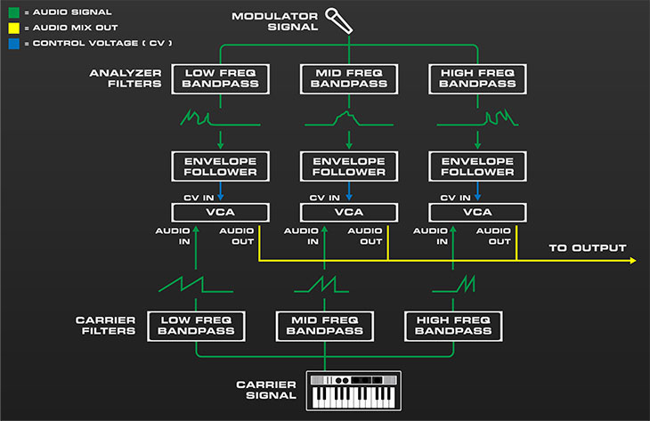
A vocoder imparts the frequency spectrum of one sound onto another. In the diagram above, a microphone's frequency spectrum (i.e., speech), is imparted onto the sound of a synthesizer playing a basic sawtooth-wave patch. Let's break down what's happening:
At the bottom of the image, a synthesizer plays constant notes using a harmonically rich sawtooth wave. This is referred to as the "carrier" signal. The synthesizer output is multed to three bandpass filters (aka, BPFs). Because each filter only allows a certain region of the audio frequencies to pass through, this effectively splits the signal into low-, mid-, and high-frequency components (an actual vocoder has many more individual bandpass filters which we'll discuss later, but for our example, we've simplified the circuit to three bandpass filters). Each of these feeds an individual voltage-controlled amplifier (VCA), which acts as volume control that gets louder or softer depending on a separate incoming control voltage (CV). If the VCA's CV inputs are not currently receiving a control voltage, the VCA's are "closed," that is, no sound is allowed to travel through. This is why a vocoder doesn't make any sound unless you're holding down keys and speaking into the mic.
Now let's examine what happens when the split-up synthesizer carrier signal is playing into the VCAs and the mic is spoken into. When the user speaks into the microphone, the mic signal is multed into an identical second set of bandpass filters and also split into frequency bands - this is called the "modulator" signal (the original refers to this as the "program" signal, as does VM 16 Channel Rackmode Vocoder), and the modulator BPF's are referrred to as "analyzer" filters, because they're effectively analyzing the incoming mic signal. The low-, mid-, and high-frequency components each travel to individual envelope followers. The envelope followers convert the constantly oscillating, up and down AC audio signal voltages to single-polarity DC control voltages proportional to each frequency band's overall signal volume. These control voltages are routed to the carrier signal VCA CV ins and (here's where the magic happens) cause the carrier (synth) bandpass filter volumes to mimic the volume and frequency spectrum of the modulator signal filters. The audio outputs of all VCA's are then mixed together and travel to the vocoder output.
The preceding is a simplified explanation. First and foremost, if we want good fidelity from our vocoder (voice intelligibility is the main factor here), more than three sets of bandpass filters (bands) are necessary. Most commercially available vocoders have at least 10 bands, and the VM 16 Channel Rackmode Vocoder has (you guessed it) 16. Taking into consideration that this means 32 individual bandpass filters, 16 VCAs, and 16 envelope followers, and it's easy to see why hardware vocoders have historically been pricey affairs.
There are few other things going on under the hood that help with speech intelligibility and general fidelity of a vocoder, including adding highpassed noise and modulator signal to clarify S sounds (the Hiss you see on the front panel), weird EQ curves, etc. Suffice to say, theoretically making a vocoder isn't too complicated, but making a really great-sound vocoder is indeed tricky business.
An important aside is that a vocoder does not detect specific note pitches in the modulator signal, nor will they be audible in the vocoder output. This means that if you're using a mic as a modulator source, it makes no difference whatsoever whether you speak words or sing, on key, off key, or otherwise (good news for modern TikTok artist-types!). The actual notes you'll hear will always be those of the carrier signal. When using a microphone (or recorded speech), the best results are usually obtained by speaking very clearly and exaggerating diction. TL;DR: singing ability has no effect on vocoder results.
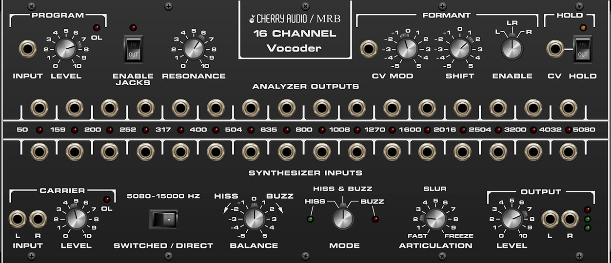
Program and Carrier Inputs and Controls
Program / Input and Level- This is where you'll patch the incoming modulator signal and set its gain level. Note that "program" is oddball 70s terminology - in just about any other context, it's referred to as the "modulator" signal, and we will refer to it as such in this user guide to (hopefully) reduce confusion.
If you're using the vocoder to create standard "robot voice" effects, the modulator signal should be either a live microphone input or an audio track containing spoken or sung audio. This would typically be audio routed from your DAW's sidechain input, which in turn appears at the Audio Sources jacks in Voltage's top IO Panel. With that in mind, you'll want to patch a cable from one of the Audio Sources jacks to the Program / Input jack. With that said, this is Voltage Modular, so depending on what kind of madness you're getting into, the Program input source can be any signal in voltage. For best results, we recommend signals with dynamically changing rhythmic and/or pitch content.
Set the level so the overload lamp (OL) only flashes occasionally; optimizing the modulator level will result in the best speech intelligibility.
Carrier / Outputs and Level- This is where you'll patch incoming carrier signals and set its gain level. The signal may be mono or stereo; if the signal is mono, either input jack may be used.
The Level knob sets the volume of the incoming carrier signal, aka, the signal that gets modulated. By its nature, a vocoder is a subtractive synthesizer - that is, it applies numerous filters to the carrier that constantly remove varying sections of the audio spectrum. Because of this, it's best to use a carrier signal with a dense harmonic spectrum - sawtooth waves are used most frequently because of their rich even-order harmonics. Square and pulse also make good carrier tones. Conversely, we don't recommend using dull or excessively thin sounds as carrier signals.
The Rackmode Vocal Source Oscillator and Poly Vocal Source Oscillator are ideal carrier sources. In particular, combining their unique "glottal" waveform and its accompanying controls with the 16 Channel Vocoder enables stunningly realistic vocal timbres.
Stereo Signals and the VM Vocoder:
The original 16 Channel vocoder was strictly a mono affair - mono program and carrier inputs and mono out. This arrangement is swell for standard robot vocal effects. But vocoders can also be used to great effect on stereo carrier signals - anything from a string section to an entire song mix, thus the carrier side of VM Rackmode 16 Channel Vocoder includes stereo inputs, and the output section include stereo outputs. However, the modulator side (i.e. Program input) is mono only. This is done because, frankly, a stereo modulator source greatly increases complexity and CPU usage "under the hood," and (in our opinion) doesn't offer much sonic benefit.
As an example, one common vocoder application is to use a drum loop to modulate static synthesizer chords; if the modulator drum loop was stereo, there would be little to no audible difference in the vocoder output (keep in mind that if the unvocoded, dry drum loop was still used in the mix, there's no reason you couldn't retain its stereo component - simply mult it into the the vocoder's modulator input monophonically).
One more thing to bear in mind is that when using "stereoizing" effects with a vocoder (most commonly, stereo chorus, which sounds great), they'll sound much better when patched after the vocoder's final output, because their high frequencies won't be potentially dulled by the vocoder bandpass filters.
Enable Jacks / Analyzer/Synthesizer Bandpass Filter Patching
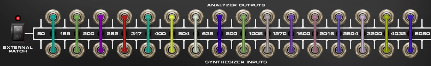
Each vertical jack pair represents one of the 16 pairs of bandpass filters. The numbers to the left and right of each jack indicate the lower and upper frequencies it passes (like any analog filters, they have a "slope" on either side, so adjacent BPF frequencies will overlap to some degree depending on the Resonance control setting). For example, the first BPF on the left passes from 50 Hz to 159 Hz, the second BPF passes from 159 Hz to 200 Hz, etc. The LEDs between the jacks illuminate with varying intensity, dependent on the current signal strength of each band, e.g., the VCA control voltage amount.
VM 16 Channel Rackmode Vocoder's External Patch switch completely disconnects the modulator-side control voltages from the corresponding carrier-side VCA's (the blue arrows in the How A Vocoder Works overview diagram at the top). This allows the modulator and carrier BPF filters to be rerouted or "cross-patched" in any desired configuration, opening many creative possibilities.
The Analyzer/Synthesizer bandpass filter jacks will only function when the Enable Jacks switch is enabled.
The patching configuration shown above is identical to the normal "hardwired" internal patching when the External Patch switch is disabled.
Resonance
Resonance- Sets the width or “Q” of all bandpass filters of both banks simultaneously. Narrow bandwidths let less audio through, whereas wider bandwidths let more audio through for a denser sound. A good analogy would be to imagine water running through a comb with wider or narrower tooth spacing.
Formant Shift and CV Control
As we've established, the 16 Channel vocoder contains 48 bandpass filters (16 on the program side, and 32 on the carrier side). The Formant section Shift knob simultaneously changes the center frequency of all 48 bandpass filters down or up .
This control isn't present on the original unit and it's a very nice effect. It sounds great when the Shift knob is dynamically varied, so we added a CV input.
CV input jack and attenuator- Allows an incoming CV to control formant shift setting, either positively or negatively.
Mod Routing- Routes CV mod to either the left, right, or both filter banks.
Shift- Simultaneously adjusts the frequencies of all bandpass filters.
Hold and CV Control
CV input- Allows an incoming CV > 2.5V to control the Hold switch explained below.
Hold- Enabling the Hold button freezes the current state of the carrier VCAs. This is useful if you'd like to infinitely sustain a carrier filter curve without turning blue in the face endlessly singing a note with a mic. Specifically, it's useful for sustained, choral "aah" type pads.
Hiss & Buzz
One caveat of vocoders is that they don't reproduce non-pitched sibilant sounds very well (i.e., anything with an "S" sound). These S sounds lie at the top of the audible frequency range, and they're very important for intelligibility.
There are two ways vocoders compensate for this:
The original made use of both of these techniques. Non-pitched sibilants are referred to as hiss, whereas pitched "body" sounds are referred to as buzz. The clever bit (as our English friends say) is that the vocoder automatically detects whether the incoming modulator audio is non-pitched hiss sound, or a pitched buzz sound, and instantaneously switches between these signals, resulting in excellent intelligibility and overall fidelity. This switching is always active, with the current signal mode displayed by the green and red LEDs adjacent to the Hiss and Buzz mode switch positions. There a couple of controls that enable, disable, and set the mix level of each component:
Switched/Direct - 5080-15000 Hz- When in the Switched (left) position, only the highpassed white noise signal is heard when S sounds are detected in the modulator signal (i.e. green Hiss LED is glowing)
When in the Direct (right) position, highpass-filtered direct modulator audio is mixed into the output in addition to the aforementioned highpassed white noise signal, resulting in more pronounced sibilance. If you're speaking or singing into a mic, you'll hear a faint "ghost" version of your voice in the vocoder output (this is easiest to hear with the Mode knob set to Hiss position). Note that the highpass filtered direct audio is always on if the Direct switch is enabled - that is, it doesn't turn on and off via the hiss detector circuit like the highpassed white noise signal.
Balance- Sets the mix of hiss and buzz signals when the Mode knob is in the Hiss & Buzz position. It has no effect if the Mode knob is set to the Hiss or Buzz positions.
Mode- Determines whether hiss, buzz, or both are heard in the vocoder output.
Hiss- Highpassed white noise signal is constantly audible, i.e., it's not switched by hiss detector circuit. We don't find the Hiss position to be super useful for final vocoder audio, but it's an effective way to "solo" and hear exactly what's happening in the hiss component.
Hiss & Buzz- Hiss detector alternates between signals depending on the incoming modulator audio content.
Buzz- No white noise or highpassed mic modulator signal mixed in with sound.
For most situations, we recommend parking the Mode switch at the Hiss & Buzz position and using the Balance knob to dial in the desired amount of hiss vs. buzz signals. The buzz signal is usually where the sonic interest comes from, but hiss can be very helpful for intelligibility.
Slur
Articulation- This sets the decay/release time of the modulator side envelope followers. In use, this equates to the overall responsiveness of the vocoder to modulator signals - fast articulation times equate to a tight, responsive sound, whereas slower times result in "lazier" recovery from transients. Setting to max Freeze position is essentially the same as enabling the Hold switch described below.
Output
Level- Sets the master output level. It's a good idea to carefully optimize the Program, Carrier, and Output gain for best fidelity.
L/R output jacks- Sets the master output level. It's a good idea to carefully optimize the Program, Carrier, and Output gain for best fidelity.