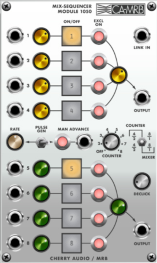
As its name implies, the 1050 Mix-Sequencer module is a unique combination of an eight-channel mixer and a sequencer that can enable and disable stages either manually, by CV, or via its own internal clock. It's functionally similar to the Voltage Modular Eight To One switch module, but with the addition of attenuators on each step, an onboard clock, and perhaps most importantly, the ability to simultaneously enable steps in any combination. When its internal clock is enabled, it can cycle through a single eight-step pattern, or dual four-step patterns. (My aunt was a regional Dual Four-Step champion in Galveston.)
Stage/Input Controls
The stage controls are repeated in each of the eight stages. Like that awful "Life Is Beautiful" music festival that I can hear from my house, multiple stages can be simultaneously active.
Input jack- Plug incoming signals in here. Inputs can be control signals or audio signals.
Input attenuator knobs- These act as level controls for incoming signals.
Step On/Off buttons- These enable or disable the signal. If the Pulse Gen (i.e. internal clock) is disabled (toggle switch right), the buttons can manually be turned on and off. If the Pulse Gen is enabled (toggle switch left), the buttons will step sequentially with their patterns dependent upon the Counter and Counter/Mixer toggle settings.
Excl On buttons- Excellent? Excelsior? Excedrin? Actually "excl" is short for exclusive. The buttons function like the solo buttons of a standard mixer channel - they shut off all other currently enabled stages. If the Counter/Reset switch is in the far left 4/2 position, the Excl On buttons only affect stages within their group of four. (i.e., the 1-4 and 5-8 stages are independent)
SUPER-DUPER IMPORTANT THING ABOUT STEP ON/OFF BUTTONS, SO LIKE, READ THIS:
When the module is in "manual" mode (Pulse Gen disabled, toggle switch right), you'll probably notice that one of the stages cannot be disabled (or two of the stages, if the Counter/Mixer switch is in one of the four-step positions). To shut off the "stuck" stage(s), set the Counter control to the Off position. (This is exactly how the original 2500 modules works, so please don't trash us on your favorite synth forum for this.)
1-4 and 5-8 Mix Volume knobs- These act as master volumes for each four-stage group.
Output jacks- These output the signal for the currently active stage.
Pulse Gen and Stage Advance
The 1050 Mix-Sequencer includes an onboard clock, aka "Pulse Gen" that can step through the stages like a sequencer (we're refer to it as a clock). If the clock is disabled, the module behaves much like a conventional mixer with channel on/off (the big square buttons) and solo buttons (the red Excl On buttons). If the Pulse Gen switch is enabled (toggle left), it behaves more like a sequencer, stepping through and enabling/disabling stages as it steps. The controls in the center of the module define the stepping behavior.
Rate- Sets the Pulse Gen (clock) speed when enabled.
Pulse Gen- Setting the toggle left enables the internal clock. Setting the Counter knob to Off and the toggle to right position disables counting (advancing).
Man Advance button and CV jack- Advances the active step forward when the button pressed or a trigger or gate CV is sent to the jack. The Pulse Gen must be disabled for the Man Advance to work.
Counter- Sets the number of stages when Pulse Gen or Man Advance is used. Setting it to the Off position will disable the Pulse Gen and Man Advance, so if these appear to be dead, be sure to set the Counter to a number. If the Counter/Mixer switch is set to one of the four-step settings, setting the Counter to anything higher than 4 won't make a difference - it will behave as if it was set to 4.
Counter/Mixer switch- Sets the grouping of the eight stages when using Pulse Gen and Man Advance as follows:
4/2 (toggle left)- Configures stages 1-4 and 5-8 as two independent four-step groups; signals are routed to their respective 1-4 and 5-8 Output jacks.
4/2 (toggle center)- Configures stages 1-4 and 5-8 as two independent four-step groups. All stages mixed to upper and lower Output jacks, master out level knobs affect each Output jack.
8/1 (toggle right)- Moves through all steps sequentially, dependent upon Counter knob setting. Mixed output is the same for upper and lower Output jacks, master out level knobs affect each Output jack.
Declick- Adds an adjustable duration of crossfade when changing stages to prevent nasty clicks. The knob is set to 10% by default. This feature is not present on the original 2500 module, but set the knob to zero and you'll quickly understand why we added it.
Link In- Not to be confused with the not-cleverly-misspelled 90s band "Linkin Park," the Link In jack uses a dynamic CV to enable synchronization between modules. Specifically, the 1027 Clocked Sequential Controller module is intended to be the master clock, and its Link Out jack should be patched to one or more 1050 Mix-Sequencer and/or 1026 Preset Voltage modules.
Note that plugging a source into the Link In jack overrides the Pulse Gen and Manual Advance button and CV jack. When using linking, the Counter knob should be set to any value other than Off; its number setting will have no effect on timing or step length.
If the Mix-Sequencer is set to one of the 4/2 modes, and the 1027 Clocked Sequential Control (can't I just type "sequencer?") is set to greater than four steps, the Mix-Sequencer will "wrap around," and begin counting again from step 1, but both modules always reset to step 1 at the same time. For example, if the 1027 master is set to six steps and the 1050 set to one of the four-step modes, the 1050 will count 1-2-3-4-1-2 then back to 1.
The Link In jack can also be slightly misused for step control with positive-polarity LFO waves - the positive polarity saw wave from any of the 1004 or 1023 oscillators is perfect for this. The idea is to use waves that change voltage over their duration, so square waves won't work well (they'll simply alternate between two positions). Adding an attenuator module (such as the Attenuverter) between the LFO and the Link In jack allows control of the number of steps as well.