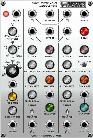
The 1045 Synthesizer Voice Module packs an entire 2500-style voice into one compact module. Though it sacrifices a few controls and inputs, it essentially contains the equivalent of a 1004 oscillator, a 1006 lowpass filter, two 1003 envelope generators, and a VCA.
Inputs, Outputs, and Controls
Oscillator
The 1045 Synthesizer includes a single oscillator.
Oscillator enabled lamp- Illuminates when the Oscillator Wave selector knob set to any position other than Off.
1V/Oct jack- Accepts a CV input for pitch. Typically this would come from the Pitch jack in the IO Panel CV Out section, or from a sequencer CV out.
Frequency / Coarse and Fine- The Coarse control sets the base frequency over a nine-octave range, in octave increments. The Fine control allows continuous fine pitch control and is configured as a "multiplier" with center position being nominal and a range of 1/2 pitch to the left or double the pitch to the right (i.e., +/- one octave).
Oscillator Wave selector- Five waveforms are available: sine, triangle, square, ramp, and pulse waves. The pulse wave's duty-signal (i.e., width) can be set using the Pulse Width knob. The Off position disables the oscillator - this is useful for using other sections to process signals from other modules.
Freq Mod jack and attenuator- Used for externally modulating the oscillator frequency. It's useful for adding vibrato with an LFO, siren noises, envelope-controlled pitch sweeps, etc. The attenuator knob is bipolar; it allow positive (turn right) or inverted voltage control (turn left). It defaults to center zero position.
All of 1045's mod inputs are exponential, that is for a given mod input voltage, the mod amount increases as frequency increases. For example, if the base frequency is 1000 Hz, and a bipolar wave is applied to the mod CV input, the frequency falls to 500 Hz and rises to 2000 Hz. Because audio frequencies are inherently exponential in nature, the resulting frequency rises and falls exactly one octave.
Pulse Width (PW)- This sets the width or "duty-cycle" of the pulse wave (the very bottom waveform on the panel). It has no effect on any other waveform. Its default setting of 50% outputs a perfect square wave, rich in odd-order harmonics. Moving the knob left or right narrows its width as well as the thickness of sound until it almost disappears at its extremes.
Osc Out jack- Raw oscillator waveform output, dependent on wave selector switch settings.
Envelopes
The 1045 Synthesizer includes two independent envelope generators: the one the left controls filter cutoff frequency; the one at far right controls VCA amplitude. That said, they include independent CV ins and outs and can be patched to control other destinations. Here's how they work:
When a gate voltage is sent to the Gate In jack (or the Gate button is held), the envelope generator outputs a voltage that changes dynamically according to the settings of its four stages.
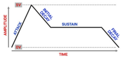
The Attack stage defines how long it takes for the output voltage to rise from 0 to 5 volts. Once the attack stage reaches 5V, it moves to the Initial Decay phase, which defines how long it takes to fall from 5V to the setting of the Sustain phase. Unlike the Attack, Initial Decay, and Final Decay phases, each of which define a time, Sustain Level simply sets the held voltage level following the Attack and Initial Decay phases - this usually equates to the envelope output level while holding down a key on a keyboard controller. The Final Decay Time knob defines the the length of time it takes for the voltage to fall back to 0V when the gate input voltage is removed (typically when you let go of a key on a keyboard controller).
Gate input jack (gate wave icon)- This is where you'll patch gate voltages to initiate the envelope generator cycle. Most often this will come from the IO Panel Gate output.
The gate input jacks for the filter and VCA envelope generators are normalled, as indicated by the bidirectional arrows on the panel. Patching a single gate signal into either one of the jacks automatically connects to both. The gate inputs function independently if separate cables are patched to each input (i.e. the normalled connection is broken).
Trigger input jack (spike wave icon)- This is where you'll patch trigger voltages to reset the envelope generator cycle. This can originate from the IO Panel Trig output, a sequencer, or other modules.
As with the gate input jacks, the trigger input jacks for the filter and VCA envelope generators are normalled. Patching a single trigger signal into either one of the jacks automatically connects to both. The trigger inputs function independently if separate cables are patched to each input (i.e. the normalled connection is broken).
"What's the difference between a gate and a trigger?"
A gate is a constant voltage. If you're playing a keyboard, it remains high (i.e. +5V) as long as the key is held down.
A trigger is a rapid spike of +5V. It's useful for a number of things (like turning stuff on and off, triggering "one-shot" drum sounds or modules, or restarting the envelope).
Attack Time- Defines the length of time for voltage to rise from 0V to 5V when the gate voltage is applied.
Initial Decay Time- Defines the length of time for voltage to fall from the Attack Time stage 5V peak to Sustain Level setting.
Sustain Level- Sets the held voltage level following Attack Time and Initial Decay Time phases.
Final Decay Time- Defines the length of time for voltage to fall from Sustain Level to 0V when gate is released. This is typically called "release" on most other synths.
Single Multiple trigger modes switches- In a situation where a note is already held down (gate input is high), these determine whether or not the envelope retriggers when a new note is played. When set to Single, new notes will not retrigger the envelope; when set to Multiple the envelope retriggers every time a new note is played, regardless of previously held notes.
–––––––––––––––––
IMPORTANT
Unlike most envelope generators, both the Gate and Trigger CV inputs must be connected, or else the 1045 will behave a little strangely.
It's important to remember that the 2500 modules were designed during the infancy of analog synthesizer development, so they don't always work exactly like their modern counterparts.
If Voltage Modular's IO Panel Trig CV output isn't connected to Trigger CV input, it will work fine in Single mode, but Multiple trigger mode will not work correctly (the Attack Time control won't do anything, and the Initial Decay Time knob will behave as the Attack Time control).
For proper envelope and triggering behavior:
Set the Voltage IO Panel Single/Multi selector to Single.
Patch the IO Panel Gate and Trig CV outputs to the 1045 Gate and Trigger CV inputs, respectively.
Because the Trigger CV input restarts the envelope from the decay phase, the Gate and Trigger CV inputs can be combined for interesting rhythmic effects. For example, a note could be held with the keyboard (via the IO Panel Gate CV out) while retriggering from a sequencer for emphasis on particular beats.
It should go without saying that you won't hurt anything if you hook it up "wrong," but the envelope generator may not behave as expected.
Filter
The filter section is ARP's take on the classic 24 db/oct transistor ladder filter. It has the "fat" sound associated with this design.
Filter In- Audio input to the filter. The internal oscillator is normalled to the filter input, so it isn't necessary to patch a cable - this input is intended for patching external signals. Note that this connection does not "break" the connection from the onboard oscillator. The onboard oscillator signal is combined with the filter input jack.
1V/Oct jack- Accepts a CV input for scaling the cutoff frequency to match ascending notes. Typically this would come from the Pitch jack in the IO Panel CV Out section, or from a sequencer CV out.
Filter fc (cutoff frequency)- Sets the cutoff frequency. Since this is a low-pass filter, all frequencies lower than this value will be allowed to pass through the filter while frequencies higher than the cutoff will be attenuated at a rate of 24db per/octave.
Resonance- Turning this knob up emphasizes sound energy at and around the cutoff frequency by adding feedback from the filter’s output back to its input. With higher settings, modulation of the cutoff frequency becomes more pronounced. Filter Resonance can cause loud squelches at high settings, so be careful.
Env Ampl- Sets the amount of cutoff frequency modulation from the filter mod envelope generator (to the left of the filter section).
Frequency Mod CV jack and attenuator- These are CV input jacks and attenuators for externally controlling cutoff frequency. The attenuators are bipolar - center position is zero; turn right for positive CV or left for inverted (negative) CV values.
Filter Out- Output of the filter signal.
VCA
A voltage-controlled amplifier with authentic vintage style overdrive characteristics.
VCA In- Audio input to the VCA. The filter output is normalled to the VCA input, so it isn't necessary to patch a cable - this input is intended for patching external signals. Note that this connection does not "break" the connection from the onboard filter. The onboard filter signal is combined with the VCA input jack.
Drive- Sets the amount of inherent overdrive. Its default setting of 32.2% is very close to the overdrive inherent to a vintage 2500 VCA.
Amplifier Gain- This is an initial gain setting for the voltage-controlled amplifier. Typically this will be set to zero, as the VCA level will usually be controlled by an envelope. Opening it up is useful for drones, or when setting pitches on a sequencer.
Ex/Lin- These select the "curve" of the amplifier's response as the input CV rises from 0 to 5V. Ex or exponential curve is a close representation of how the human ear perceives volume, whereas Lin or linear response curve is equally proportional across the voltage input range. You'll likely want to use the Lin setting for modulation or control voltage situations, and use the Ex setting when an envelope generator is used to control an audio signal with the amplifier.
Env Ampl- Sets the amount of amplitude modulation from the amp mod envelope generator (to the left of the VCA section).
VCA Mod CV jack and attenuator- Controls VCA amplitude. This can be used for patching an alternate envelope generator, or for amp mod via LFO's, etc. The attenuator is bipolar - center position is zero; turn right for positive CV or left for inverted (negative) CV values.
VCA Out- The output of the VCA, i.e. 1045's final output.