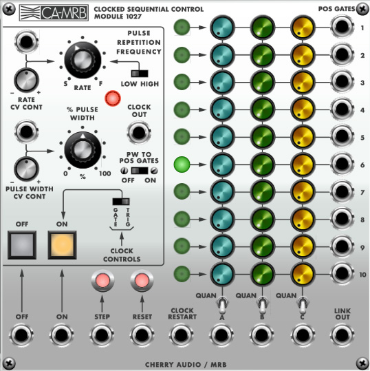
The 1027 Clocked Sequential Control is an impressively wordy name for a "sequencer." With ten steps, arranged in three columns, it can output three independent CV's per step. It has a CV-controllable onboard clock, as well as a separate gate CV out for each step. Because the ARP 1027 is one of the earliest CV sequencers, it has a few unique quirks, but by and large, it functions like most modern step sequencers.
Sequencer Step Controls, Inputs and Outputs
Controls are repeated for each of the ten steps. In case you're wondering why they chose ten steps instead of the more musically sensible eight, it's because the 1027 is built upon the newfangled (in 1970) "decade counter" chip which, as its name implies, has ten stages, so they used all the available stages in the design (if you've ever explored DIY hardware sequencers, you've probably encountered the ten-step 4017 IC-based Baby 10 sequencer - this design uses the same type of decade counter IC).
Stage active lamp- Glows to indicate the current step.
Control Voltage knobs- Each vertical column of knobs sends a separate voltages to the corresponding A, B, or C output jack, depending on which stage is currently active. These can be set from 0 to +5V.
POS Gates- These output a 5V gate when the step is active. They can be used for a number of functions, but the most important application is to set the number of sequencer steps. This can be done by patching the POS gate after the max number of steps to the Reset jack. For example, to set an eight-step sequence, patch a cable from jack nine to the Reset jack. (Don't think we didn't notice that POS Gate is a funny name, but there wasn't enough room on the panel to fit "position." Huh huh.)
Quantize switches- In the off (toggle down) position, the CV knobs can be freely set to any voltage between 0 to +5V. If the CV outs are used to control oscillators, this can make tuning melodies difficult. In the Quan position (toggle up), the CV knobs move in 1/12V steps , which equates to semitones.
Output A/B/C jacks- The jacks at the bottom of each knob column outputs the voltage for the currently active stage.
All Other Controls, Inputs and Outputs
Rate knob- This sets the Pulse Repetition Frequency, which is a super hoity-toity way of saying "speed."
Rate CV Control jack and attenuator- Allows CV control of the Rate knob. The attenuator knob is bipolar - center setting=off.
Low/High range- Sets the range of the Rate knob. Low is pretty slow and more useful for switching-things kind of applications; high is typically what you'll want for playing melodies.
Rate/Active lamp- Flashes at the current rate when the sequencer is playing.
% Pulse Width- Sets the width (aka, duty cycle) of the clock wave at the Clock Out jack, with a setting of 50% equivalent to a perfect square wave. If the clock out is being used to trigger an envelope generator (or directly control a VCA), the pulse width sets the note length.
Pulse Width CV Control jack and attenuator- Allows CV control of the % Pulse Width knob. The attenuator knob is bipolar - center setting=off.
PW To Position Gates- In the On position, the pulse width setting affects the duration of gate voltages sent to the POS Gates outputs. This control isn't present on the original 1027 - we're added it to address a sometimes-annoying quirk of the original design, and we'll explain why it's useful in the Gating Steps With The VM1027 section below.
Off/On and CV ins- Turns the onboard clock on and off - the equivalent of play and stop buttons. These can be triggered via the corresponding jacks beneath.
Clock Controls / Gate/Trigger- This determines the behavior of the On button. In Trig mode, clicking or sending a trigger CV to the On button CV jack latches playback - i.e., the sequencer stays in play mode with a single click or trigger CV input until the Off button is clicked, or a CV is received at the Off CV jack. When set to Gate mode, the sequence only plays when the On button is held, or a gate voltage is present at the On CV jack.
At either setting, the sequence always starts at its current position and does not reset to step one unless the Reset button is clicked, or a CV is sent to the Reset CV jack.
Step button and CV in jack- Clicking the button or sending a trigger or gate CV to the CV in jack advances the sequence one step. This is useful for configuring tuning (with the clock in Off mode), or using an external source to move through steps. The Step CV jack essentially functions as an external clock input.
Reset button and CV in jack- Clicking the button or sending a trigger or gate CV to the CV in jack resets the sequence to step one. This can be used in conjunction with the POS Gates to set the number of sequence steps.
Clock Restart CV in jack- Though the Reset button and CV jack explained above will reset the pattern to step one, this doesn't reset the internal clock (it essentially "waits" until the next clock step). This behavior is inherent to the original 1027 design. This can cause timing issues, particularly if you want a sequence to begin the instant a key is pressed, for example. For this reason, we've added the Clock Restart CV input; sending this a trigger or gate voltage instantly restarts the internal clock to guarantee tight timing.
Link Out- The Link Out jack allows synchronization between modules. Specifically, the 1027 Clocked Sequential Controller module is intended to be the master clock, and its Link Out jack can be patched to one or more 1026 Preset Voltage and/or 1050 Mix Sequencer modules.
Because Link Out jack uses stepped voltages to control other modules, further control of step ranges is possible by adding an attenuator between connections.
Gating Steps With The VM1027
Perhaps the biggest difference between the 1027 and most modern sequencers is its lack of dedicated per-step gate buttons and an accompanying gate CV output. This leaves us a couple of options for gating note envelopes on and off:
Gating Envelopes With Clock CV Out- The easiest way to gate envelopes is to patch the Clock Out jack to the gate in of an envelope generator. The % Pulse Width knob can be used to set the length of time a gate voltage is sent to the envelope generator, i.e. the overall note length (this will of course be affected by envelope generator settings.) The problem with this arrangement is that individual steps cannot be disabled - all sequence steps play a note.
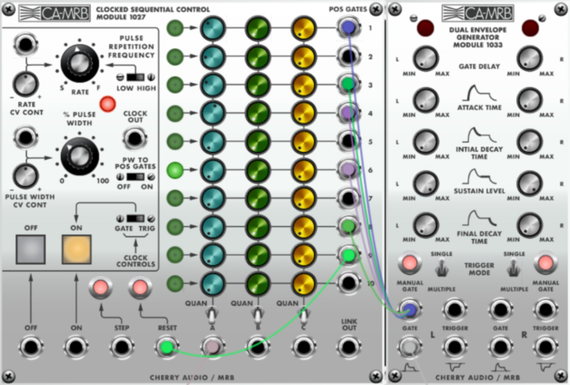
Routing POS Gate Outs To An Envelope Generator- Patch individual cables from the POS Gate jacks of all steps you'd like active to the gate input of an envelope generator. This works fine, but with two caveats: as can be seen in the above image, it creates a mess of cables, and isn't really conducive to experimenting with turning steps on and off. The other potential issue is that two or more consecutive steps will output a single gate that lasts the duration of all consecutive steps. In other words, multiple consecutive steps won't individually re-trigger an envelope generator. The good news is that we addressed this by adding the PW To POS Gates switch. With this enabled, the POS Gate voltage durations correspond to the % Pulse Width knob setting, enabling individual envelope triggering for consecutive notes.
(If you're not hip to the [SHIFT]-click-drag shortcut for simultaneously moving or deleting multiple cable connections, now would be swell time to check it out.)As a little historical aside, setting up sequences in this manner with the original 2500 was a little easier because it didn't use jacks and cables - it used a large grid of 20-position slide switches. In this example, note gate steps could be enabled by switching the desired position gate outputs to the same horizontal switch row.
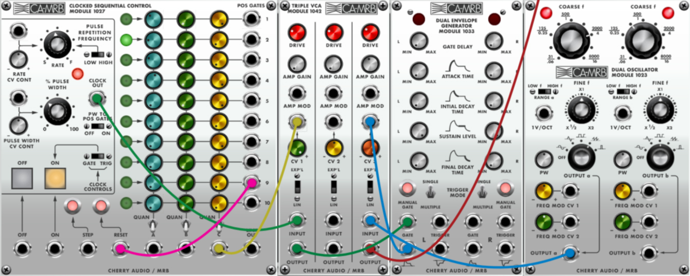
The Fancypants Clock-Through-VCA Method- Patch the Clock Out jack to the input of a VCA, and the out of the VCA to the gate in of an envelope generator. Now patch a cable from one the the vertical CV knob row output jacks to the CV control in of a VCA. To enable a step, turn up the appropriate CV knob.
The only downside is that a column of CV knobs is "lost," but the good news is that it's easy to gang up multiple 1027's for as many CV columns as needed by patching the Clock Out jack to the Step CV in jacks of one or more 1027's.
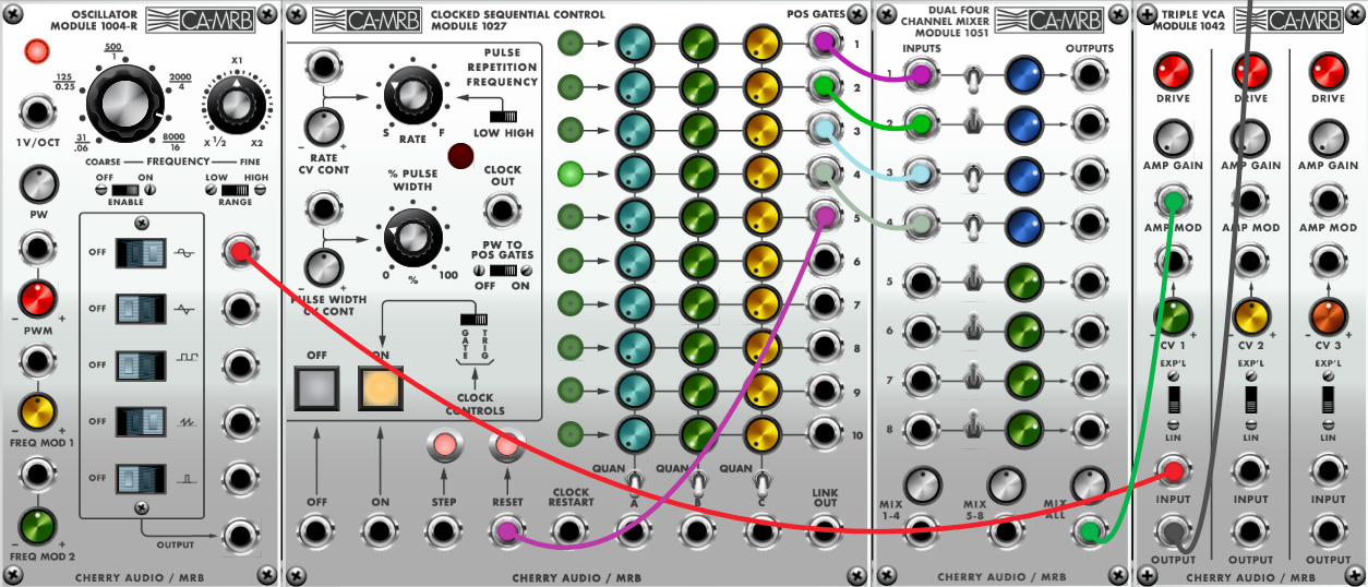
The Mixer Switches Method- This approach uses the 1051 Dual Four Channel Mixer's toggle switches to switch steps on and off. POS Gates 1-4 are patched to mixer inputs 1-4, and POS Gate 5 is patched to the Reset jack to create a four-step sequence. Oscillator output is patched to VCA Input, and VCA Output is patched to the IO Panel Main Out. The mixer's Mix All output is patched to VCA Amp Mod control input, and steps are enabled or disabled using the mixer toggles.