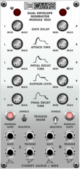
The 1033 is an ADSR envelope generator with two identical and fully independent envelopes. It functions exactly like the original 2500 version, and has a few operational quirks which we'll explain. It's basically identical to the 1003 envelope generator module, but adds a Gate Delay knob which allows a "pause" of up to three seconds prior to the initiating the attack phase. If you're not familiar with the operation of envelope generators, here's an overview:
When a gate voltage is sent to the Gate In jack (or the Gate button is held), the envelope generator outputs a voltage that changes dynamically according to the settings of its five stages.
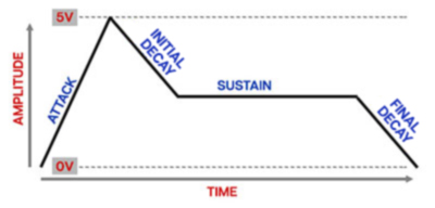
The Gate Delay knob adds a "pause" of up to three seconds prior to the initiating the Attack phase. The Attack stage defines how long it takes for the output voltage to rise from 0 to 5 volts. Once the attack stage reaches 5V, it moves to the Initial Decay phase, which defines how long it takes to fall from 5V to the setting of the Sustain phase. Unlike the Attack, Initial Decay, and Final Decay phases, each of which define a time, Sustain Level simply sets the held voltage level following the Attack and Initial Decay phases - this usually equates to the envelope output level while holding down a key on a keyboard controller. The Final Decay Time knob defines the the length of time it takes for the voltage to fall back to 0V when the gate input voltage is removed (typically when a key is released).
Inputs, Outputs, and Controls
As the "dual" in its name implies, the 1033 module contains two completely independent envelope generators, with identical controls, inputs, and outputs.
Gate indicator lamp- Illuminates to show an incoming gate voltage of > 1V has initiated the envelope.
Gate Delay- Adds a "pause" of up to three seconds prior to the initiating the attack phase. Removal of a gate signal during the delay cancels the envelope and resets the delay timer.
Attack Time- Defines the length of time for voltage to rise from 0V to 5V when the gate voltage is applied.
Initial Decay Time- Defines the length of time for voltage to fall from the Attack Time stage 5V peak to Sustain Level setting.
Sustain Level- Sets the held voltage level following Attack Time and Initial Decay Time phases.
Final Decay Time- Defines the length of time for voltage to fall from Sustain Level to 0V when gate is released. This is called Release on just about every synthesizer on the planet.
Manual Gate button- Manually initiates the envelope generator cycle for as long as it's held. This is the same as sending a gate voltage to the Gate In jack.
Trigger Modes switch- In a situation where a note is already held down (gate input is high), these determine whether or not the envelope retriggers when a new note is played. When set to Single, new notes will not retrigger the envelope; when set to Multiple the envelope retriggers every time a new note is played, regardless of previously held notes.
–––––––––––––––––
IMPORTANT
Unlike most envelope generators, both the Gate and Trigger CV inputs must be connected, or else the 1033 will behave a little strangely.
It's important to remember that the 2500 modules were designed during the infancy of analog synthesizer development, so they don't always work exactly like their modern counterparts.
If Voltage Modular's IO Panel Trig CV output isn't connected to Trigger CV input, it will work fine in Single mode, but Multiple trigger mode will not work correctly (the Attack Time control won't do anything, and the Initial Decay Time knob will behave as the Attack Time control).
For proper envelope and triggering behavior:
Set the Voltage IO Panel Single/Multi selector to Single.
Patch the IO Panel Gate and Trig CV outputs to the 1033 Gate and Trigger CV inputs, respectively.
Because the Trigger CV input restarts the envelope from the attack phase, the Gate and Trigger CV inputs can be combined for interesting rhythmic effects. For example, a note could be held with the keyboard (via the IO Panel Gate CV out) while retriggering from a sequencer for emphasis on particular beats.
It should go without saying that you won't hurt anything if you hook it up "wrong," but the envelope generator may not behave as expected.
–––––––––––––––––
Gate input jack- This is where you'll patch gate voltages to initiate the envelope generator cycle. Most often this will come from the IO Panel Gate output.
Trigger input jack- This is where you'll patch trigger voltages to reset the envelope generator cycle. This can originate from the IO Panel Trig output, a sequencer, or other modules.
"What's the difference between a gate and a trigger?"
A gate is a constant voltage. If you're playing a keyboard, it remains high (i.e. +5V) as long as the key is held down.
A trigger is a rapid spike of +5V. It's useful for a number of things (like turning stuff on and off, triggering "one-shot" drum sounds or modules, or restarting the 1033 envelope).
In the case of most envelope generators, the gate voltage is usually all you need to be concerned about, but the 1033 is a bit quirky and requires both for proper multi-triggering behavior. Please see the section that says IMPORTANT in giant letters for more information about this gate and trigger business.

Normal/Inverted out- These are the envelope voltage outputs. The standard jack (icon going up from centerline) outputs voltage ranges from 0V to +5V, whereas the inverted jack ((icon going down from centerline) is inverted, with output ranging from 0V to -5V.