
The 1036 Sample & Hold Random Voltage module is a synthesis tool that repetitively “samples” an input signal and outputs its voltage until triggered again. This module features two identical sample & holds and includes a built-in white noise generator - the most common "sample" source for creating random voltages. It also includes two independent clock sources - both sample & holds can run from one clock or they can run independently. The original 1036 module also features and extensive front-panel circuit schematic, which is helpful, should it ever need servicing...
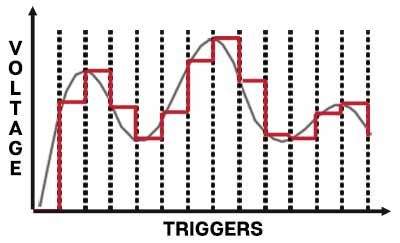
Kidding aside, we've illustrated how a sample & hold works to make its operation easier to understand. In the image below, the smooth gray line shows a continuous input signal. Each time the module is triggered the current voltage is “sampled” and “held” until the next trigger. The red line shows the stepped output signal.
Inputs, Outputs, and Controls
Clock Freq- The clock "samples" the incoming signal at intervals defined by its current setting. Its range is from 0.1 Hz - 1000 Hz (depending on the current Clock Multiplier slide switch setting).
Clock Multiplier Switch- Center position is nominal; moving the switch left divides clock frequency by 10, moving it to the right multiplies clock frequency by 10.
Clock Frequency Mod CV jack and attenuator- Allows CV control of the clock frequency. The attenuator is bipolar with center position = no modulation.
The Sampling Switch
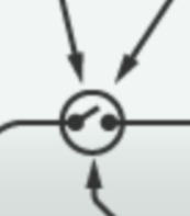
If you're familiar with circuit schematics, you probably recognize this as the symbol for a switch. This represents the "sampling" the input voltage. Looking at the panel, we see three arrows around its perimeter - each of these represents a way the switch circuit can be triggered, via either the momentary Single Sample button, the onboard clocks, or the Sample In jack. Note that all three trigger inputs are simultaneously active.
Single Sample button- This momentary button "grabs" an instantaneous sample of the input signal - either white noise (if the Int Random Sig knob is up) or from a source patched to the Ext Sig input jack.
Clock (a) and Clock (b)- The two independent onboard clocks are used to sample input signals at regular intervals. When disabled (toggles in Off position, duh), new sample voltages are output by clicking the Single Sample button. Sample & hold B (the one on the right) can be clocked with clock (a) (both sample & holds synchronized) or clock (b) (each sample & hold running independently), or both clock (a) and clock (b) simultaneously for all manner of asynchronous sample & hold clockin' fun.
Sample In jack and Trig/Gate switch- The Sample In jack triggers sampling when it receives a CV. In Trig mode a single instantaneous sample is taken when a trigger or gate voltage is received.
In Gate mode, the sample switch is held closed as long as a gate signal is present - the audible result is that the sample and hold output "follows" the Int Random Sig (i.e. onboard white noise) and/or the Ext Sig input, until the gate voltage falls, at which time the latest value is held. This is called "track and hold".
Int Random Sig jack and attenuator- Sets the level of the internal white noise sample source. White noise is frequently used as a source in sample & holds because the resulting voltages will be completely random. The attenuator sets the amount of white noise routed to the sample & hold circuit.
Ext Sig input jack and attenuator- Allows any signal to be used as a source to be sampled. Interesting results can be achieved with any the standard "rising" or "falling" oscillator waves at sub-audio speeds (i.e. ramp, saw, triangle, or sine waves). Endless semi-melodic permutations can be created by varying the frequency of the waveform in combination with the sample & hold clock speed. The attenuator knobs sets the amount of external signal routed to the sample & hold circuit.
Note that the onboard white noise signal and external signals can be combined.
Clock Out- An output for the internal clock circuit for syncing to other modules.
S/H Out- Output voltage of the sample and hold circuit.