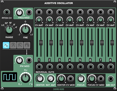
The Additive Oscillator lets users combine the first eight partials in the harmonic series to create composite tones with a choice of sine, triangle, or variable-width pulse waves. Inspired by 70’s “West Coast” synthesizer modules, it includes separate outputs for each partial, and allows the partial levels to be modulated in a number of creative and intuitive ways. First we’ll explain the function of each control, then we’ll explore the Additive Oscillator in use.
Keyboard CV - Standard 1V/octave CV input for pitch control.
Range - Sets the octave range in standard footage increments. The Lo setting is intended for modulation purposes and will generally be below audible range. (unless you’re a whale and can hear 1Hz)
Wave Select Buttons - These select sine, triangle, or variable-width pulse wave. Only one can be selected at a time.
Pulse Width Control and Display - This knob allows manual control of pulse width. Center position will generate a 50% square wave; rotating left or right results in narrower pulse-widths. The waveform display shows the current width of the pulse wave.
Freq Mod - Applying CV’s here modulates the base pitch of the oscillator; in other words, all partials are affected equally. This can be used for basic vibrato or siren effects with sub-audio modulation speeds, or wilder FM cross-mod when using audio-range signals.
PW Mod - Short for pulse-width, this mod input allows real-time modulation of the pulse wave. It won’t have any audible effect if the sine or triangle wave is selected.
Top Row CV Jacks and Attenuator Knobs - These CV inputs allow level modulation of each partial. The small CV Amt knobs are CV attenuators. Incoming CV’s are combined with slider settings.
Partial Level Meters - These give a visual display of partial volume levels.
Partial Level Sliders - Sets the levels of each partial in the harmonic series. 1 is the the fundamental frequency, 2 is the second harmonic, etc.
Partial Individual Out Jacks - Separate audio outs for separate processing of individual partials. Note that these are affected by the partial slider volume settings.
Center - Defines the center frequency of the slider “peak.”
Init Amt - Sets the initial amplitude of the the slider “peak.”
Center CV Jack and Attenuator Knob - CV input for external modulation of Center frequency.
Focus - Sets the width of the slider “peak.”
Focus CV Jack and Attenuator Knob - CV input for external modulation of “peak” width.
Please see the “Modulation Time C’mon” section below for more information about Center, Focus, and slider peak.
Mix Out - Audio output of the mix of all partials.
Basic Use
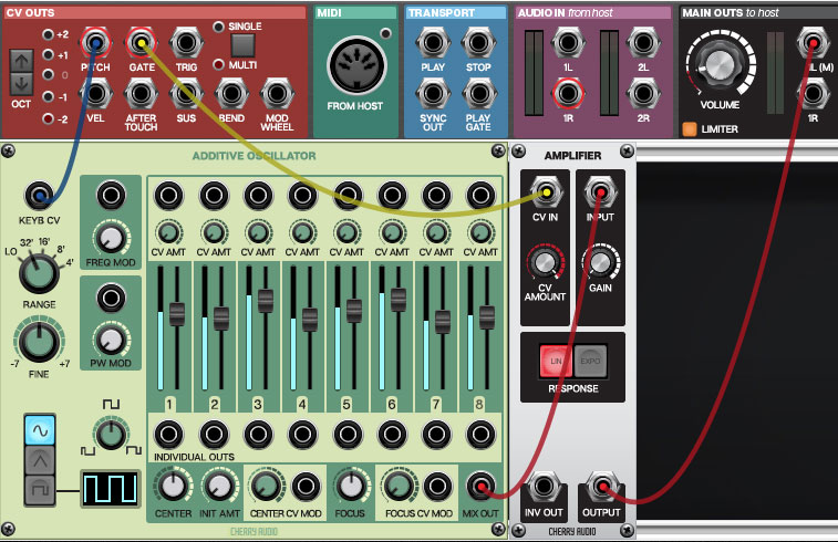
Let’s start by setting up a basic patch consisting of an Additive Oscillator and a voltage-controlled amplifier, as shown below:
Pitch from the IO Panel goes to Keyb CV input, Mix Out is routed to amplifier Input, and gate from the IO Panel goes to the amplifier’s CV In. Amplifier audio out is routed to IO Panel Main Outs to host.
If you ignore the modulation options, the Additive Oscillator is super easy to use, and operation is just like using a standard analog oscillator - in fact, it’s effectively the same as opening eight individual oscillators and tuning each to partials one through eight of the harmonic series (for example, 100Hz, 200Hz, 300Hz, 400Hz, 500Hz, 600Hz, 700Hz, and 800Hz).
With the above patch set up, go ahead and play the Additive Oscillator. Adjusting the fader levels affects the volume of each harmonic, sort of like a vintage tonewheel organ on steroids. Notice the blue level meter to the left of each slider - this may seem superfluous now because the meter is displaying the static level of the adjacent fader, but their usefulness will become clear once we begin exploring the Additive Oscillator’s modulation possibilities.
Modulation Time, C’mon
If you’re a seasoned synthesist, all of the controls at the left of the panel should be familiar. Things start getting nutty when the Additive Oscillator’s modulation controls are used. Let’s begin with the CV level mod jacks and wee knobs at the top of the panel:
Partial Level Mod Controls and CV Attenuators
The CV input jacks above each partial slider allow CV control of each individual partial level. The small knob beneath each CV jack is an attenuator for setting the amount of CV voltage. Note that partial level CV mod works additively with the current fader level setting. Of course this easy to see by looking at the blue level meter, which always shows the actual output level.
Center and Focus Mod Controls and CV Attenuators
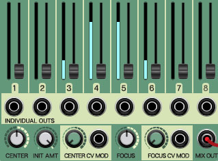
Things get pretty awesome here! The Center and Focus controls essentially let you create a “peak” of faders and move the “peak” up and down across the faders either manually or via CV. It’s much easier to demonstrate than it is to explain, so let’s set the controls as shown below:
Notice that all sliders are set at zero, but the meters show a peak - partials three and six are quiet, while four and five are louder. Adjusting the Center Init Amt knob adjusts the level of the peak. Turning the Center knob sweeps the peak up or down across the partials. Remember that, like the partial level CV mod at the top of the panel, Center and Init Amt control settings combine with the existing fader settings and level CV mod. (This is why we zeroed the slider settings for this demo, but of course these can set any way you like.)
You may have noticed that sweeping the Center control sounds really cool, which is why there’s a Center CV Mod in jack and attenuator knob. This can be modulated by anything that outputs a voltage, but an LFO at a slow rate is a good place to start.
The Focus knob adjusts the peak width, from one partial wide to all partials at full blast. To its right is a Focus CV Mod in jack and attenuator knob, allowing CV modulation of Focus width.
Advanced Additive Oscillator Madness
Try routing the two sections of a Mini LFO to Center CV Mod and Focus CV Mod. This simple setup will go a long way, especially if you use the triangle wave on one of the CV ins and the square on the other.
Embellish the above routing by routing another LFO to the PW Mod CV in and selecting the pulse wave on the Additive Oscillator.
If you’ve purchased the Misfit Audio Drum Modules package, the Drum Trigger Sequencer is a wickedly fun modulation companion - it's eight individual channels enable each harmonic partial to have its own complex rhythmic sequence. BTW, after experimenting with this, we added a couple of milliseconds of lag into the level CV ins to prevent clicking with hard on/off gate voltages.
We’ve saved the wackiest for last. The Additive Oscillator’s partial separate outputs can be routed back into any of its mod inputs for all manner of audio-range frequency modulation madness. Try routing these to the Freq Mod and PW Mod inputs as well as individual partial CV ins.