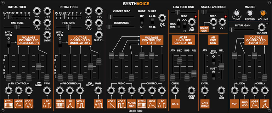
Synth Voice is a powerful, self-contained monophonic synthesizer. It's inspired by the classic ARP 2600 synthesizer, and like the 2600, features "semi-normalled" audio and modulation paths that enable fast and often wild sound creation. It includes two oscillators, a multimode filter, ADSR and AR envelope generators, a low-frequency oscillator, sample and hold, ring modulation, and a simulated spring reverb. Because it's part of Voltage Modular, any and all of its individual sections can be combined with other modules for maximum creativity.
If you don't want to read this entire guide, please have a look at the "Semi-Normalled Patching" section below, because Synth Voice's patching works a little differently than most Voltage Modular modules.
Semi-Normalled Patching
If you've worked with cable patch bays in recording studios, you may be familiar with the concept of semi-normalled connections. This means that certain connections are invisibly patched by default if no cable is plugged into a jack, but plugging a cable into the jack interrupts the "normal" signal flow and replaces it with the patched cable. The orange boxes along the bottom of the Synth Voice panel indicate what the source is if nothing is plugged into the the jack above. In other words, if nothing is plugged into the jack, it's as if the jack isn't there. If an audio or control signal is plugged into the jack, the normalled source is overridden, effectively disconnecting it.
This applies to Synth Voice in two ways:
External IO Panel Normalled Connections- The following output jacks in the IO Panel CV SOURCES section are normalled to modulation input jacks at the bottom of the Synth Voice panel.
IO PANEL - CV SOURCES OUTPUT
NORMALLED MOD DESTINATIONS
Pitch
VCO 1 Pitch, VCO 2 Pitch, VCF Pitch
Gate
ADSR Gate, AR Gate (Trig)
Trig
AR Gate (Trig) [if AR Trig switch is enabled]
Mod Wheel
Low Frequency Oscillator depth [if Mod Whl switch is enabled]
Plugging a jack into one of the normalled connections at the IO Panel does not disconnect it from Synth Voice. For example, you could patch the IO Panel Pitch and Gate outputs to other modules without interrupting the normalled connection to Synth Voice.
Internal Synth Voice Normalled Connections- All of the orange boxes+jacks along the bottom of the panel, as well as the Sample and Hold section Noise Gen are normalled connections, with the default source indicated in the orange box. Plugging a cable into the associated Synth Voice jack disconnects the normalled source and replaces it with the patched cable.
Almost all of these have an attenuator slider directly above them affecting the amount of either the normalled signal or the currently patched cable.
Voltage-Controlled Oscillators 1 & 2
Synth Voice includes two super-wide range oscillators that accurately model the imperfect waveforms of vintage ARP synthesizers.
Initial Freq- Sets the basic pitch of the oscillator, displayed in traditional organ footage. Lo will be beneath the audible range and allows the oscillator to be used as a mod source.
Fine Tune- This can be used to fatten up two-oscillator patches by detuning a small amount, or for "building-in" a set interval. Its range is a smidge over a fifth, up or down.
Waveform Output Jacks- Voltage-Controlled Oscillator 1 (VCO 1) includes triangle, ramp, sine, and pulse waves. VCO 2 includes triangle, saw, sine, pulse waves, and sub-octave square- this a 50% square wave one octave below the other VCO 2 waves. It is not affected by pulse width settings.
Like a vintage ARP 2600, the oscillators do not have switches for wave selection. Instead, VCO 1's sawtooth wave and VCO 2's pulse wave are normalled to the VCF audio ins and gain sliders (at the bottom left of the VCF section). To select a different oscillator wave, patch a cable from the appropriate VCO wave output jack to any of the VCF Audio input jacks. This overrides the "preset" normalled routing.
Note that VCO 1 and VCO 2's ramp and saw waves sound exactly the same at audio-range frequencies, but the reversed shapes are useful for rising or falling modulation when the oscillators are set to Lo initial frequency settings and used as mod sources.
Sync (VCO 2 only)- Feeding a wave or signal to this force resets the start of the waveform to the beginning of its cycle. Most often used to create the "sync sweep" oscillator sounds made famous in The Cars' "Let's Go" (or Kraftwerk's "Neon Lights" and No Doubt's "Just A Girl"), by routing the output of another oscillator to the Hard Sync input and sweeping the pitch of the first oscillator.
Hard Sync is also useful when creating drum and percussion sounds to ensure that the wave starts precisely at the beginning of its cycle.
FM Control/PWM Semi-Normalled Inputs- Mod inputs at the bottom of the panel. The slider control above each jack is an attenuator, affecting the amount of the normalled source, or if a cable is plugged into the jack, the amount of the signal from the patched source.
The table below shows the default sources and destinations for VCO 1 and VCO 2:
MOD SOURCE NAME
NORMALLED SOURCE
NORMALLED DESTINATION
VCO 1 - Pitch CV
IO Panel CV Sources/Pitch
VCO 1 frequency - no attenuation slider
VCO 1 - ADSR
Synth Voice ADSR envelope generator
VCO 1 frequency
VCO 1 - VCO 2 Sine
Synth Voice VCO 2 sine wave output
VCO 1 frequency
VCO 1 - LFO
Synth Voice LFO output
VCO 1 pulse width
VCO 2 - Pitch CV
IO Panel CV Sources/Pitch
VCO 2 frequency - no attenuation
VCO 2 - AR
Synth Voice AR envelope generator
VCO 2 frequency
VCO 2 - VCO 1 Pulse
Synth Voice VCO 1 pulse wave output
VCO 2 frequency
VCO 2 - LFO
Synth Voice LFO output
VCO 2 pulse width
Glide- Also known as "portamento," glide delays the voltage change between pitches for a sliding effect. Synth Voice includes separate Glide controls for each oscillator - applying glide to only one oscillator is nice effect.
Pitch CV In- This switch connects or disconnects the normalled IO Panel Pitch CV connection. This defaults to on position, for standard keyboard (or sequencer) playing. Turning it off is useful for drones or sound effects when you don't want oscillator pitch to be affected by keyboard CV.
Though the Glide slider is situated above the normalled Pitch source and jack, it is not an attenuator for it, but it is in the signal path, so it will affect the normalled pitch CV or any signal plugged into the Pitch FM jack.
PW Initial- This sets the width or "duty-cycle" of the pulse wave. It has no effect on any other waveform. This defaults to 50%, i.e., a perfect square wave. Moving the slider up or down narrows its width as well as the thickness of sound until it almost disappears at its extremes.
Voltage-Controlled Filter
Synth Voice's filter section models the early "ladder"style filter used in early ARP synthesizers. It can be switched between lowpass and highpass modes, with 12- or 24-db per octave slopes.
If you're not familiar with how filters work, a lowpass filter allows frequencies below the cutoff frequency setting to pass through, but blocks frequencies above the cutoff frequency. A highpass filter does opposite: it allows frequencies above the cutoff frequency setting to pass through, but blocks frequencies below the cutoff frequency. In practice, this means a lowpass filter is useful for removing high frequencies, and a highpass filter is useful for removing low frequencies. Modulating the cutoff frequencies via envelope generators, low-frequency oscillators, and more opens the door to endless sound possibilities.
Cutoff Freq- Sets the frequency where attenuation begins. Attenuation occurs above (Iowpass mode) or below this frequency (highpass mode).
Resonance- Emphasizes sound energy at and around the current cutoff frequency by adding feedback from the filter's output back to its input. At lower settings, this can be used to create mild resonances such as those heard in acoustic instruments. At more extreme settings, resonance can create a pure sine wave at its own frequency (you can adjust its pitch with the Cutoff knob). Be careful with this knob as it can get loud at extreme settings.
Mode- The nature of how a filter works is that frequencies "fall off" above or below the cutoff frequency. Slope adjusts the steepness of this slope. Set to lowpass mode, a 12db per/octave filter has a shallower slope, whereas a 24db per/octave filter has a steeper slope (as well as more pronounced character with the resonance knob turned up).
VCF Out jack- The direct audio out of the VCF section.
Audio and Control Semi-Normalled Inputs- These are the audio and frequency modulation inputs at the bottom of the filter section. The slider control above each jack is an attenuator, affecting the amount of the normalled source, or if a cable is plugged into the jack, the amount of the signal from the patched source.
The table below shows the filter's default sources and destinations. The Audio section inputs effectively function as a mixer for Synth Voice's oscillators, noise generator, or any other audio sources patched to the semi-normalled inputs.
AUDIO/MOD SOURCE NAME
NORMALLED SOURCE
NORMALLED DESTINATION
Audio - VCO 1 Saw
Synth Voice VCO 1 saw wave
VCF audio input
Audio - VCO 2 Pulse
Synth Voice VCO 2 pulse wave
VCF audio input
Audio - Noise Gen
Synth Voice white noise generator
VCF audio input
Control - Pitch CV
IO Panel CV Sources/Pitch
VCF cutoff frequency
Control - ADSR
Synth Voice ADSR envelope generator
VCF cutoff frequency
Control - LFO
Synth Voice LFO output
VCF cutoff frequency
ADSR Envelope Generator
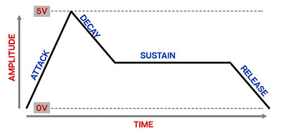
A standard "ADSR"-style envelope generator most often used to shape amplitude or filter curves. If you're not familiar with the operation of envelope generators, here's an overview:
When a gate voltage is received, the envelope generator outputs a voltage that changes dynamically according to the settings of its four stages.
The Attack stage defines how long it takes for the output voltage to rise from 0 to 5 volts. Once the attack stage reaches 5V, it moves to the Decay phase, which defines how long it takes to fall from 5V to the setting of the Sustain phase. Unlike the Attack, Decay, and Release phases, each of which define a time, Sustain simply sets the held voltage level following the Attack and Decay phases - this usually equates to the envelope output level while holding down a key on a keyboard controller. Finally, the Release knob defines the the length of time it takes for the voltage to fall back to 0V when the gate input voltage is removed (typically when you let go of a key on a keyboard controller).
Keep in mind that the envelope generator moves through its attack and decay segments and holds at the sustain level as long a 5V gate voltage is being received. It moves to the release segment when the gate voltage is removed (i.e., 0V gate voltage).
Its controls are as follow:
"A" (Attack) slider- Defines the length of time for voltage to rise from 0V to 5V when the gate voltage is applied.
"D" (Decay) slider- Defines the length of time for voltage to fall from the Attack stage 5V peak to Sustain stage setting.
"S" (Sustain) slider- Sets the held voltage level following Attack and Decay phases.
"R" (Release) slider- Defines the length of time for voltage to fall from Sustain level to 0V when gate is released.
The table below shows the default mod destination:
MOD SOURCE NAME
NORMALLED SOURCE
NORMALLED DESTINATION
Control - Gate
IO Panel CV Sources/Gate
ADSR Envelope Generator
ADSR Out jack- The envelope generator's output voltage.
AR Envelope Generator
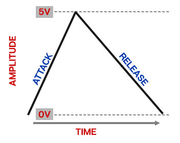
A simple envelope generator with attack and release segments only. It may seem "stripped down," but AR generators are very useful for basic envelope applications, particularly drum and percussion sounds (which Synth Voice excels at).
The AR envelope functions a little differently than the ADSR envelope. If the Sustain switch is on, it moves through the attack segment when a 5V gate is applied and remains at maximum as long as the gate voltage is present (equivalent to an ADSR envelope with its sustain control set to maximum). If the Sustain switch is off, it moves through the release segment regardless of whether the 5V gate voltage is present.
Its controls are as follow:
"A" (Attack) slider- Defines the length of time for voltage to rise from 0V to 5V when the gate voltage is applied.
"R" (Release) slider- Defines the length of time for voltage to fall to 0V following the attack segment (Sustain switch off) or when gate voltage is removed ((Sustain switch on).
Trig- Enabling this causes the AR envelope to move through both of its segments regardless of the gate voltage length. This means trigger signals (i.e. extremely short gates) can be used to run through both stages of the AR envelope. The (Trig) label on the orange mod input legend refers to the gate behavior when the Trig switch is enabled.
Sustain- Adds a 5V sustain segment following the attack segment for as long as gate voltage is high. The release segment occurs when the gate voltage is removed.
Manual Trigger- Sends a gate signal to both the ADSR and AR envelope for as long as the button is held. This can be useful for testing sounds or playing on the fly.
The table below shows the default mod destination:
MOD SOURCE NAME
NORMALLED SOURCE
NORMALLED DESTINATION
Control - Gate (Trig)
IO Panel CV Sources/Gate
AR Envelope Generator
AR Out jack- The envelope generator's output voltage.
Voltage Controlled Amplifier
You can think of the VCA as a "gate" to start, stop, and shape the volume of audio or control signals. Applying a simple 5V gate voltage will abruptly open and close the VCA; the CV output of an envelope generator lets you shape audio and control signals with more finesse.
Initial Gain- Sets the static gain of the amplifier; a good analogy would be opening a faucet. For standard instrument-type sounds, you'll likely leave this set to minimum, as the envelope generators control signals will open the amp when notes are played. Turning up the Initial Gain is useful for "hands-off" droning sounds.
VCA Out jack- The output of the VCA. The LED next to the jack lights when a signal is present.
This VCA Out jack is Synth Voice's master out, and is not normalled to the IO Panel. You'll need to patch a cable from this output to one of the IO Panel Main or Aux Out jacks (or a mixer module patched to an IO Panel out) to hear sound.
AUDIO/MOD SOURCE NAME
NORMALLED SOURCE
NORMALLED DESTINATION
Audio - VCF output
Synth Voice VCF output
VCA audio input
Audio - Ring Mod
Synth Voice VCO 1+VCO 2 ring mod
VCA audio input
Control - ADSR
Synth Voice ADSR envelope generator
VCA amplitude
Control - AR
Synth Voice AR envelope generator
VCA amplitude
Ring Modulation
The Ring Mod input multiplies both oscillator signals by one another, resulting in a signal containing only the sum and difference of the two signals and not the original signals themselves. This often results in tones with unrelated harmonics which can sound harsh or out of tune, but when dialed in carefully can create sounds and timbres hard to create with other methods. For most dramatic effect, try detuning VCO 1 and VCO 2 using the Initial Freq and Fine Tune controls.
Ring mod is sourced from the VCO 1 and VCO 2 jacks in at the bottom of the filter section. If nothing is plugged into these jacks, this means the ring mod section receives the VCO 1 sawtooth wave and VCO 2 pulse wave. To send different waves to the ring mod section, patch the desired waves into the VCO 1 and VCO 2 inputs Audio inputs in the VCF section, just as you would for "normal" alternate wave selection. (sine waves from both oscillators sound particularly good with ring mod).
Low Frequency Oscillator
A low frequency oscillator or "LFO," is similar to an audio oscillator, but it typically runs at frequencies below the range of human hearing, and it isn't used an audio source. Instead, its cycling waveforms are used as a control source to add modulation to oscillators, filters, and amplifiers.
A typical application would be to slightly modulate an oscillator’s frequency to create vibrato (pitch modulation), or to modulate a VCA’s amplitude to create a tremolo effect (amplitude modulation). Modulating the cutoff frequency of a filter can create a dubstep-style wobble, or if modulated very slowly, long sweeping tonal shifts.
Frequency- Sets the rate of the LFO from 0.01 Hz-20 Hz. This guy can get REALLY slow.
Mod Wheel switch- Turning this on normals the IO Panel CV Sources/Mod Wheel output to LFO depth control. This makes setting up Synth Voice for pitch modulation with a mod wheel easy - turn the switch on, patch a cable from the LFO Out to one or both of the oscillator FM mod jacks, and push up the corresponding FM slider. (Oscillator Pulse Width or VCF mod is even easier, because these have normalled internal routings; simply push up the appropriate fader in the VCO or VCF sections). If the Mod Wheel switch is on and your controller's mod wheel is at zero, the LFO won't have any signal output, thus... if the LFO doesn't seem to be working, make sure the Mod Wheel switch is in the off position (or push up your controller's mod wheel).
Waveform Selector- Switches the LFO's output to triangle or square wave. The triangle wave is bipolar (i.e. its voltage sweeps above and below 0 volts); this works well for pitch modulation because the pitch rises and falls above and below the center frequency. The square wave is unipolar, that is, it only goes up then returns to zero; this makes it easy to set up pitch trills or octaves. (Setting up a bipolar square wave for alternating octave pitch modulation is difficult because the high note gets higher and low note gets lower as mod depth is increased.)
Out jack- CV output of the LFO. You may not need it, because the LFO CV out is normalled to VCO 1 and VCO 2's pulse width controls, as well as VCF frequency mod, but patching a cable from the jack lets you select other destinations such as VCO pitch, VCA amplitude, or external modules. The LED next to the jack gives a visual indication of the LFO rate.
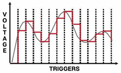
Sample and Hold- The sample and hold section repeatedly “samples” the input signal voltage, and continuously outputs that voltage until it is triggered to sample again. This duration between samples is adjustable with the Frequency slider source. Sampling can be triggered externally with a CV or audio signal. Note that when we say "sample," we're referring to a simple incoming voltage - this isn't an audio sampler that you can sample and playback beats with. (Though this is the basic principle of how digital audio samplers operate).
In the image above, the smooth gray line shows a continuous input signal. Each time the module is triggered, the current voltage is “sampled” and “held” until the next trigger. The red line shows the stepped output signal.
Frequency- Sets how often the incoming signal is sampled. This could also be referred to as the sample or clock rate. Unlike many hardware analog synths with sample and hold, Synth Voice's sample frequency isn't tied to the LFO section; the sample and hold section has its own independent internal LFO clock.
Though it's not at the bottom of the panel with the rest of the normalled connections, the Noise Gen+In jack is a normalled connection so here's another swell table:
AUDIO/MOD SOURCE NAME
NORMALLED SOURCE
NORMALLED DESTINATION
Noise Gen
Synth Voice white noise generator
sample and hold sample source
White noise is commonly used as a sample source with sample and hold modules because it creates completely random voltages. If applied to oscillator pitch, this results in note sequences with random pitches. Filter cutoff frequency modulation is another common use (one famous example is the percolating note sequence at the beginning of Emerson, Lake, and Palmer's "Karn Evil #9," better known as "welcome back my friends, to the show that never ends..."). LFO waves can also be used as signal sources - oscillator ramp and sawtooth waves at sub-audio rates can be used to create interesting rising and falling modulation patterns.
Out jack- CV output of the sample and hold. The sample and hold's output isn't normalled to any destinations, so you'll need to patch this to the desired mod destination with a cable.The LED next to the output jack flashes at the current sample frequency.
Master Section
Tune- The master tuning knob affects both oscillators simultaneously and has a range of a half-step up or down.
Reverb- This is an accurately modeled spring reverb. Like a real spring reverb, certain frequencies will excite and "ring" in funny ways sometimes. In other words, it isn't intended to precisely replicate the acoustics of The Royal Albert Hall. Note that dry signal remains constant; the knob mixes the reverberated signal from 0-200%, allowing really wet sounds.
Volume- This is post-VCA, and regulates the volume of all sound coming from Synth Voice.