Poly FM Station is a digital oscillator inspired by the Yamaha DX/TX-series synths. It is mostly identical to the "mono" FM Station module.
Like the classic Yamaha synths of the 80s, it uses frequency-modulation (FM) synthesis to create tones. In their day, they were giant step forward for and delivered an entirely new palette of sounds. Unfortunately, the original Yamaha synths gained a reputation for being difficult to program and as a result, most users simply used the factory presets.
Though FM synthesis is inherently less intuitive than standard subtractive analog synthesis, most of the difficulty in programming the original Yamaha synths had more to do with the minimal user interface than the actual synthesis method itself. In order to cut costs, almost all synth manufacturers of the era were switching from knob-per-function interfaces (think Minimoog/Prophet-5) to interfaces where a single slider or up/down buttons in conjunction with a small alphanumeric LCD was used for sound programming. This made creating sounds tedious at best, and given their large number of parameters, next to impossible on the Yamaha FM synths.
With this in mind, we designed Poly FM Station to be as easy to understand and program as possible - all of its main parameters are indicated by colored bars, some of which change colors to clarify their current function. In plain English, Poly FM Station is really fun and easy to use. We had a blast developing it and playing it - we hope you enjoy it as much as we do! Because it's basically identical to the mono version of the FM Station module, we'll generically refer to it as simply as "FM Station."
One more note: You'll likely need a fairly large number of envelope generators to optimally use the mono or poly FM Station modules. We contemplated building envelopes directly into the module, but this would've necessitated either hiding them behind tabs or pop-ups, or making a really large module, neither of which sits well with our "make all controls visible and grabbable at once" design philosophy. Instead, we created the EG Station module in mono and poly versions. Intended to sit directly beneath FM station, its eight ADSR envelope generators should be plenty to cover any EG mod needs when using FM Station. That said, the EG Station modules can of course be used in conjunction with any other Voltage modules.
FM Synthesis Theory Nerdfest
Here we'll cover the basics of how FM synthesis works. You don't need to read this section to use FM Station, but it will greatly help your understanding, and we promise, no math equations, because as Butthead once said, "If I wanted to do math I'd go to thgool, huh-huh."
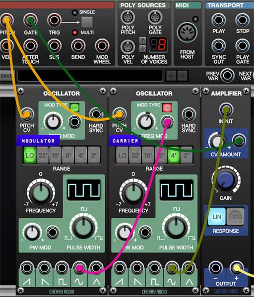
The underlying concept of FM synthesis is much like using the wavering output of a sine wave low-frequency oscillator (LFO) to modulate the pitch of an audio oscillator for vibrato. The LFO's rate is below the threshold of hearing (i.e. less than 20Hz), so you're able to clearly hear its up and down effect on the audio oscillator. In the patch below, the oscillator on the left is set to Lo range, and its sine wave output is routed to the second oscillator's Freq Mod input, creating a basic sine wave with vibrato.
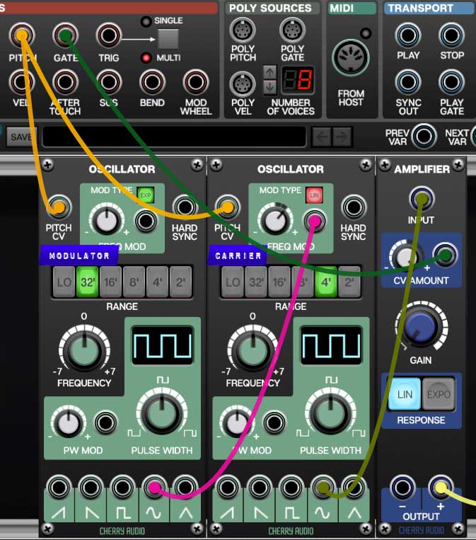
The patch shown below is exactly the same, but the modulating oscillator's Range control has been changed to the 32' setting, aka audio-rate modulation. In other words, its effect on the audio oscillator is no longer heard as vibrato- instead it changes the tonal color of the basic sine wave by creating additional frequencies known as "sidebands." The character of these sidebands can be altered considerably by manipulating the second oscillator's frequency modulation depth as well as changing the modulation oscillator's frequency. This modulating-one-oscillator-with-another-oscillator in various combinations is the basis of FM synthesis.
You may have also noticed the Modulator and Carrier dymo labels in the example patch. In FM synthesis, carrier refers to the oscillators used as audio sources; modulator refers to oscillators used to modulate the frequency of carrier oscillators - their audio is not directly heard.
Mod Type (aka, "I always wondered what that button was for.")
When setting up standard mod routings (i.e. vibrato, alternating pitches, etc.) a lot of us have likely clicked the Mod Type button both ways, not heard any significant effect on sound and moved along. But in the case of FM synthesis, linear mod is of paramount importance for creating musical, tonal sounds.
Exponential Mod- For a given mod input voltage, the mod amount increases as frequency increases. For example, if the base frequency is 1000 Hz, and a bipolar wave is applied to the mod CV input, the cutoff frequency rises to 2000 Hz, and falls to 500 Hz. Because audio frequencies are inherently exponential in nature, the resulting frequency rises and falls exactly one octave. This is desirable for most standard sub-audio frequency modulation, i.e. vibrato, sirens, etc., because the audio rises and falls an equal amount above and below the median pitch.
Linear Mod- For a given mod input voltage, the mod amount stays the same as frequency increases (hence the "linear" name). For example, if the base cutoff frequency is 1000 Hz, and a bipolar wave is applied to the mod CV input, the frequency rises to 1500 Hz, and fall to 500Hz. In other words, the frequency rises and falls by the same number of Hz in either direction.
In the case of our vibrato or siren effect example, linear mod works poorly, because pitch will appear lopsided - for example, it would go down an octave but only rise a fifth.
To state it plainly, expo mod causes notes to go way out of tune as the mod amount is increase, whereas linear mod stays in tune and remains musical. (To be fair, audio-rate expo mod is great for creating laser sounds.) Try clicking the Mod Type switch in the demo patch above while adjusting Freq Mod depth settings and you'll instantly hear the difference.
By the way, besides being super basic, our two Voltage oscillators example doesn't really make for the best FM synth emulation, because the standard Voltage oscillator has some randomness built into its tuning and waves. This is desirable for accurately emulating an analog synthesizer, but not ideal for FM synthesis where it's best to have absolutely perfect waveforms and tuning. This is why you almost never see hardware analog FM synth oscillators - if everything isn't calibrated exactly perfect, it won't sound right or play in tune across a keyboard.
Algorithms and Operators
The preceding example patch illustrated the most basic FM synthesis configuration: one oscillator modulating another, aka one modulator modifying one carrier. Lots of great sounds can be realized this way, but it's roughly akin to an analog synth with a single oscillator. In order to expand the FM synthesis tonal palette, multiple modulator and carriers are configured in various pre-patched combinations to create more complex tones. These pre-patched combinations are known as algorithms. The carrier and modulator oscillators contained therein are generically referred to as "operators," and often abbreviated to "op."
The original Yamaha DX and TX synths were either "four-op" or "six-op." In other words, they included a total of four or six oscillators which could be configured as various combinations of carriers or modulators, depending on the currently selected algorithm. Like FM Station, the algorithms were graphically displayed on the top panel of the instrument for reference (these are actually selection buttons in FM Station, but we'll talk about that later on).
Frequency Modulation vs. Phase Modulation
The story goes that Yamaha licensed the use of the FM synthesis technology developed by John Chowning at Stanford University (FYI, the patent expired in the 90s). But oddly, Yamaha DX and TX synths don't use FM synthesis at all - they actually use the closely related phase modulation synthesis instead. What's the difference, why would they do this, and what does it mean to you? First, your bad-at-math help doc writer will attempt to explain the difference.
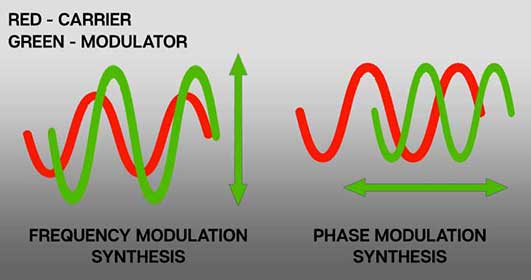
When an audio signal is frequency modulated, it can be thought of moving the wave up and down. Phase modulation can be thought of as rapidly moving the audio signal wave from side to side, thus changing the phase relationship between the two waves. Because both waves are constantly moving up and down, the effect is roughly the same on the resulting output wave.
There is one interesting quirk of phase modulation that's good be aware of - because the Freq/Ratio CV inputs affect phase, pitch changes are only audible when the mod source is moving. In other words, a constant DC voltage patched to a Freq/Ratio CV input (such as a keyboard pitch CV) won't affect pitch. Similarly, modulation waves with "straight" angles (such as sawtooth or triangle waves) will essentially sound the same as square wave mod, because their rate of change remians the same through their cycle, as opposed to a curve that's constantly changing - this is why all of FM Station's waveforms are curved.
A good analogy to understand phase mod is the doppler effect. When a car drives by honking its horn, the pitch of the horn changes as the car travels by, but if the car stops moving at any distance, the pitch of the horn remains constant. If you've ever messed with the time knob on an analog delay, they behave in the same way - pitch change is only audible while adjusting the delay time, and "catches up" as soon as you stop moving the knob. This is because a delay is performing exactly the same function - it's changing the phase (i.e. distance) of two copies of the same audio material.
Note that this only applies to the Freq/Ratio CV inputs; the Fine control bar and CV inputs are "standard" pitch CV ins (i.e. not phase mod) as is the master Freq Mod CV in at the far left of the panel.
Why did Yamaha choose phase modulation over frequency modulation? As it turns out, it takes less computational horsepower to perform phase modulation synthesis. This was an important consideration in light of the relatively limited computer horsepower available in the 80s. The other reason is that FM synthesis makes use of feedback loops for further tone colors, and with pure FM, these loops cause oscillators to go badly out of tune - with PM, tuning isn't an issue (we'll discuss these feedback loops later on). FM Station Basic Architecture
As discussed in the previous section, an "operator" is FM synth-speak for a single oscillator. FM synths generally include "pre-wired" combinations of oscillators, configured as modulators and carriers, known as algorithms. FM Station features four oscillators, making it a "four-op" FM oscillator. It includes eight selectable algorithms. Its operators each include eight selectable waveforms, and the fourth operator includes an adjustable feedback loop.
Because FM Station includes separate outputs and modulation inputs for all four operators, it can be used "a la carte," that is, if algorithm 8 is selected, all operators and mod routings can be manually patched for unlimited custom algorithm and mod routing, including multiple instances of FM Station for 8-op, 12-op, stereo or quad output routing, etc. etc.... it's Voltage Modular, what'd you expect?!?
Inputs, Outputs, and Controls
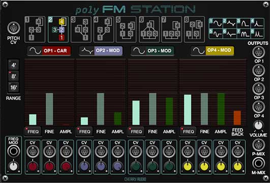
Control Bars and CV Indicator Bars
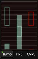
FM Station's main controls are a bit of a departure from other Cherry Audio modules. Instead of standard knobs or sliders, its main controls are colored illuminated bars. These work just like the slider controls in other modules. To change values, grab the control bar at its top edge and move it or click anywhere in the control travel to jump to the setting (this is helpful when the control is set to minimum; you won't have to precisely click the tiny visible region of the bar). Hovering the mouse on a control bar causes it to light up. The controls bars behave the same as any standard Voltage slider control- right-clicking them allows all standard operations including Perform and MIDI controller assignments.
You'll also notice the unfilled rectangular CV input indicators bars. These act as meters and display the sum of incoming poly mod CV levels in real-time. Besides being great eye candy, they're useful for quickly determining which carrier operators are making sound while under CV control.
Poly Pitch CV jack- Accepts a poly CV input for pitch. Typically this would come from the Poly Pitch jack in the IO Panel Poly Sources section.
Range- Sets the basic pitch of the oscillators, displayed in traditional organ footage. Unlike most other oscillators in Voltage Modular, there are only three range settings. This is because the Freq/Ratio controls offer a huge range of initial pitch settings, and the Range buttons are mainly intended for quick transposition.
Frequency Mod input jack and bipolar attenuator- Used for globally (i.e. all oscillators at once) modulating the base frequency. It's useful for adding vibrato with an LFO, siren noises, envelope-controlled pitch sweeps, etc. The input voltage is increased by turning from center position to the right; the input voltage is inverted and increased as the knob is turned to the left.
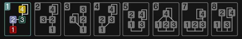
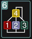
Algorithm selector buttons- The eight large diagram buttons across the top configure FM Station's operators into pre-patched routings known as "algorithms." The colored number boxes within correspond to each of the four operators; the operators in the bottom row of the diagrams represent carriers (i.e. audio sources), and operators above represent modulators (mod sources for the audio oscillators). In algorithms 5-8, all operators hooked to the horizontal line are carriers (i.e. audio sources).
Carrier oscillators are routed to FM Station's Master Volume and P-Mix (poly) and M-Mix (mono) output jacks; modulator oscillators are routed only to carrier Freq/Ratio CV inputs. All four operators are always routed to the Op1, Op2, Op3, and Op4 individual poly outputs along right side of the panel. The Amplitude control bars affect output levels in the P-Mix and M-Mix outs as well as the individual poly outs.
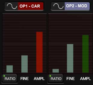
Algorithms are selected by clicking on the diagrams. The numbered operator boxes and outline frame will be colored for the currently active algorithm. A couple of things happen to help clarify which operators are currently configured as carriers and modulators in the currently selected algorithm. The text in the large colored buttons beneath the algorithm boxes changes to display CAR or MOD to indicate the status of each operator...

... and the Ampl control bars turn red for carrier operators, and green for modulator operators:
In following section, we'll go over a few of the algorithms; once you're gained an understanding of these, the others should be easy to grasp.
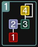
In algorithm 1, operator 1 is the only carrier. Operator 4 modulates operator 3, and operator 2 modulates operator 1. Although only operator 2 is directly modulating operator 1, the cumulative modulation of operator 4, then 3 can result in operator 2 having a highly complex modulation wave. That said, this algorithm is a good choice for simple patches where operator 2 modulates operator 1 (set operator 3 and 4 Ampl sliders to zero). This simple modulation path is essentially the same as the two-oscillator demo patch at the beginning of this guide and is a good starting point for understanding FM synthesis.
Algorithm 6 configures operators 1, 2, and 3 as audio sources, and operator 4 as a the sole mod source (with feedback loop). Algorithm 6 also resembles the gearshift pattern of my cousin's '71 Jensen Interceptor, which had chronic brake fluid issues.
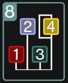
We wanted to specifically discuss algorithm 8, because it's the most interesting algorithm for the serious FM tweaker. When used with the Mix output, it's useful for additive synthesis/creating stacked chords, etc. But when used in conjunction with the individual outputs and the freq/ratio CV input jacks, it's the key to using FM Station "a la carte." Because it contains no pre-wired modulator routings, it allows users to roll their own custom algorithm routings. It's also useful when routing separate outputs to stereo panned mixers and effects, as well as combining multiple instances of FM Station for doubling or tripling the number of available operators for wildly complex FM patches.
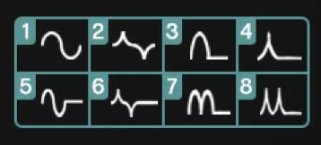
Waveforms selector buttons and panel diagram- The original DX/TX FM synths only used sine waves, but later models added extra waveforms. It should go without saying that a small number of waveforms on an FM synth isn't nearly as much of a limitation as with an analog or sample-playback synth; the original DX7 created a tremendous range of tones with sine waves only, but additional waveforms certainly expand the tonal palette, especially in a four-op configuration (as opposed to a more complex six-op configuration).

The panel display at the top right is simply a graphic displaying all eight waveforms (it's not a control of any kind). Waveforms are selected individually for each operator by clicking the black waveform selector button. These cycle forward with each click.
Freq/Ratio control bar, poly CV input and attenuator- This really a fancy name for pitch. These are tuned to the standard harmonic series of even overtones. They go from 0.25 of the base pitch all the way up to the 32nd overtone. It's unlikely you'll use the higher values as basic oscillator tones, but they higher values are intended for use as modulator sources, and they're the key to getting the signature FM bell-type sounds.
Unlike standard oscillators, the freq/ratio CV mod input isn't used for vibrato; remember that this is actually a phase modulation input, so it won't behave as expected if you patch a low-frequency oscillator or DC voltage source into it (such as a keyboard pitch CV). The main thing you'll use it for is "manually" routing the output of a modulator operator, but remember this is only necessary if the algorithm you've chosen doesn't already contian a pre-wired mod routing path.
Fine freq control bar, poly CV input and attenuator- This acts as a detune control with a range of up or down one octave, and default position at center. The CV input allows control via CV. This is a bipolar control with the middle position representing zero. Negative CV control decreases as the knob is dialed to the left; positive CV control increases as the knob is dialed to the right.
Amplitude control bar, poly CV input and attenuator- Sets the overall volume of the operator. If the operator is currently configured as a carrier, this affects the audio output level in the Mix and individual outputs. If the operator is currently a modulator, this affects the amount of modulation signal traveling to the operator it's routed to - this is the most significant sound varying parameter in FM synthesis.
The poly CV input allows control via CV. This is a bipolar control with the middle position representing zero. Negative CV control decreases as the knob is dialed to the left; positive CV control increases as the knob is dialed to the right.
Patching an envelope generator to a carrier operator is how you'll shape the amplitude curve of the sound, exactly as you would use an envelope generator in conjunction with a VCA in analog synthesis. Conversely, patching an envelope or other mod source to a modulator operator is the primary way to achieve dynamically shifting timbre.
Pay attention to the initial setting of the Amplitude control bar. If the operator is a carrier, you'll most likely want to set it to zero and patch an envelope generator to "turn the sound on and off" as you play the keyboard. Otherwise, setting the bar position above zero will result in a constant drone. You could run the Mix out to a VCA (Amplifier) module (controlled by an envelope generator), but there's really no need to, as each operator essentially contains its own built-in VCA.
Feedback control bar, poly CV input and attenuator (Operator 4 only)- FM synthesis makes use of feedback, present in operator 4 in FM Station. This routes the output of operator 4 back to its own Freq/Ratio input, with the amount set by the control bar. The resulting audio output greatly varies depending upon the currently selected waveform and amount. If the selected algorithm is using operator 4 as a modulator, this means the resulting modulation wave becomes considerably more complex than the original "unadulterated" wave.
One common FM synthesis trick is to use a sine-wave operator with feedback on its own, and turn the feedback control up about halfway, resulting in a fairly accurate sawtooth wave (hook up an Oscilloscope module to check this out). Sonically interesting results occur with different waveforms as well.
The CV input allows feedback control via CV. This is a bipolar control with the middle position representing zero. Negative CV control decreases as the knob is dialed to the left; positive CV control increases as the knob is dialed to the right.