The Cherry Audio Oscilloscope is a handy utility module featuring two inputs, range, zoom, and a freeze button for monitoring audio and CV signals. Besides looking cool (who doesn’t love looking at waveforms?), this is an extremely helpful tool for learning about modular synthesis or troubleshooting complex patches.
Inputs, Outputs, and Controls
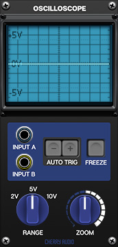
Input A and B jacks- Patch CV and audio signals here to visually monitor their voltages. Input A displays a blue waveform, and Input B displays a yellow waveform.
Auto Trig- These buttons are used to "stabilize" the visualization of the signal and are triggered from Input A only. When neither of these buttons are engaged, the voltage received is displayed without a consistent trigger or "starting point" within the display window which can sometimes appear jumpy and unstable. By engaging the - button, the oscilloscope will always show voltage starting from 0V at the left hand side and decreasing, while the + button will show voltage increasing from 0V. Having a consistent trigger point for where the voltages are displayed on the oscilloscope creates a stable waveform when monitoring cyclical signals such as oscillators. Try patching a sine-wave oscillator to the input and switching between - , +, and neither to see the difference.
Freeze- Instantly freezes the display. The signal that was present at the moment the button was clicked will be displayed until the button is turned off again.
Display window- A classic analog-style oscilloscope display showing the signal received at the Input jack. The horizontal line in the center represents 0V. Positive voltage is displayed above the 0V line while negative voltage is displayed below.
Range- Adjusts the range of voltage shown within the display. Think of this as a vertical zoom.
Zoom- Adjusts the sample length of the display window. Think of this as a horizontal zoom.