Polymode is a complete instrument module for Voltage Modular, inspired by one of the earliest 70s-era poly synthesizers. It excels at large pads, strings, and vocal-esque sounds, and its unique multiple filter implementation and mod routings gives it a sound like no other synth.
Unfortunately, the original instruments are highly unreliable as a result of their elaborate circuitry and the inconsistent quality control of 70s electronic components. They were also really expensive ($5200 in mid-70s dollars!), weighed a ton, sensitive to movement, and relatively confusing to operate. The Voltage Modular Polymode module sidesteps every one of these drawback - hooray for modern computers! Of course we've eliminated all of the reliability issues, we've updated its controls to make it MUCH easier to use, and we've added CV mod ins to almost every control for immense improvement in creative possibilities.
Polymode Signal Flow
The original instrument works like a string synthesizer (or a transistor organ) on steroids. The pitches of two fixed high-frequency square-wave oscillators are "divided-down" (i.e. slowed down) to the frequency of each chromatic note of the very top octave. Another series of IC's halves the top-octave chromatic notes to create the remaining pitches for the entire length of the keyboard. This is how just about every 60s and 70s transistor organ and 70s string synth works (as well as a number of 70s polyphonic sort-of synthesizers such as the ARP Quadra, Korg Delta, etc.).
Though it sounds convoluted, top-octave divide synthesis (referred to as "TOC") was common because it's easy and cheap from an electronics standpoint, but it can only product square waves, which severely limits the tonal palette. To get around this, the original contained a small circuit board called a "poly card" beneath each key with a custom IC chip (the "Polycom IC") that converted the square wave to a ramp wave and allowed the pulse width of the square wave to be adjusted and modulated. Because of its separate note generation for each key, TOC-based synths can't have a "mono mode," thus keyboard glide can't be implemented. Though we did not implement this "top-down" divide+waveshapers for every note in Polymode (because it's a bear on CPU load), we did go to great lengths to model the resulting idiosyncratic oscillator waves with great precision. Here's what the signal path looks like:
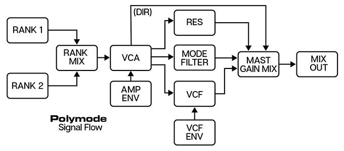
Following the oscillator "ranks" are the VCA/Amplitude Envelopes. This is unlike just about any other analog synthesizer - the VCA is almost always after the filter(s), not before. This is because the original instrument featured individual VCA/Amplitude envelopes for every note on the aforementioned poly com cards beneath each key. It also means that every single note has its own independent envelope generator. The downside of this arrangement it that the VCF cannot be self-resonating because once it started "ringing," there would be nothing to stop its sound - in a more conventional analog synth, playing the keyboard would open and close the VCA, thereby stopping sound from the ringing filter.
Following the VCA/Amplitude Envelopes are three (!) separate filters, all fed in parallel. Mixing and matching these in the Master Gain mixer section, along with the unfiltered Direct signal, is one of its niftiest tricks (in turn, this is greatly enhanced by the Master Gain mixer's CV mod inputs). The filters are:
• Resonators
• Mode Filters
• VCF
We'll go over each filter in detail later on.
The Resonators, Mode Filters, VCF are fed to the Master Gain mixer, and then to the Mix out jack in the bottom right Outputs section. The direct and filter signals can be individually routed as well.
————
Lower/Upper/Octave Bal Controls- The original included "lower" and "upper" duplicates of a number of its controls, allowing independent adjustment of various parameters at a fixed keyboard split point. Because only certain parameters had the dual controls, this resulted in a relatively half-baked attempt at keyboard split capabilities, and along with the already unusual control layout, tended to make it even more confusing. On top of this, the original had three volume sliders that split the keyboard into three volume zones (with different fixed split points than the upper/lower controls!) for extra bonus confusion. We've eliminated all of this extra-control-sort-of-splitty madness from Polymode. Trust us, you'll be much happier this way.
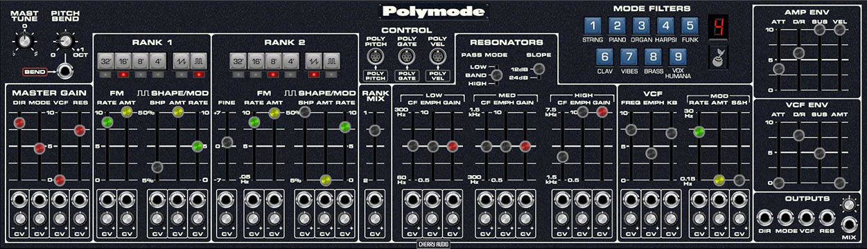
Polymode Inputs, Outputs, and Controls
Normally we would detail a module's controls from left to right, but because it doesn't exactly have a left-to-right signal flow, we'll start with the top left controls, then follow the actual signal path.
Control/Normalled Cable Connections
Polymode accepts controls signal exclusively from the IO Panel Poly Sources section. It doesn't have a "mono" mode per se, but it can easily be played monophonically by setting the IO Panel Number of Voices control to 1.
For convenience, Polymode takes advantage of Voltage Modular's cable normalling feature. Cable normalling allows us to design modules with automatic, "invisible" cables routings. By default, Polymode always has normalled poly cables routed from the IO Panel's Poly Pitch, Poly Gate, and Poly Vel outputs to Polymode's Poly Pitch, Poly Gate, Poly Vel inputs. In other words, it's the equivalent of patching cables like this...
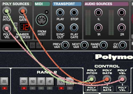
... without having to patch anything. The little green-framed boxes beneath the jacks are a visual reminder of the normalled connections (note how the boxes are the same color as the IO Panel Poly Sources section).
If you'd like to patch a signal from a source other than the IO Panel, plugging a cable into any of the Control jacks overrides the normalled IO Panel connections. If you'd like to use the IO Panel outputs with additional cables, simply patch a cable from the IO Panel output plus any other cables to the Control input jack.
Control Section
Poly Pitch- Input for poly pitch control. This is normalled from the IO Panel Poly Sources Poly Pitch output.
Poly Gate- Input for poly gate control. This is normalled from the IO Panel Poly Sources Poly Gate output.
Poly Vel- Input for poly velocity control. This is normalled from the IO Panel Poly Sources Poly Vel output.
While we're in that neck of the IO Panel woods, the Number of Voices control defines Polymode's maximum polyphony. Dialing this down can be helpful if you're experiencing CPU load issues, but you probably won't, as Polymode is pretty light on CPU.
Master Tune/Pitch Bend
Mast Tune- Sets overall tuning up or down a half-step.
Pitch Bend and CV input jack- Sets the range of incoming pitch bend data from zero to one octave. Similar to the Control section poly jacks, the IO Panel CV Sources Bend CV out jack is normalled to Polymode's Bend CV in jack (indicated by the dark orange box). This means it's connected by default, but can be overridden by plugging a patch cable into it.
Oscillators - Rank 1 / Rank 2
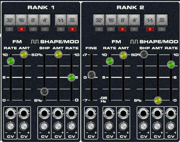
On the original instrument, each of the two polyphonic oscillator banks is referred to as a "rank," which is good ol' medieval organ terminology (as are commonly used octave footage numbers). We made the decision to greatly alter the oscillator rank section layout because frankly, the original rank controls are really confusing, and offer no improvement in functionality over the more standard layout we've implemented in Polymode. Additionally, the original instrument allowed rank 1 to produce only square and pulse waves, and rank 2 to produce only ramp waves. We felt this was a silly limitation, so we've enabled ramp/square/pulse waves either alone or in combination for both oscillator ranks. The controls for both oscillator ranks are identical with the exception of the Rank 2's Fine tune control and are as follows:
Range buttons- Sets the basic pitch range of the oscillator rank, displayed in traditional organ footage. Only one range button can be enabled at any time.
Waveform buttons- Selects ramp and/or pulse waves. These may be used independently or in combination.
Fine (Rank 2 only)- Fine-tune control for pitch. This can be used to fatten up patches by detuning a small amount, or for "building-in" a set interval. Its range is a smidge over a fifth, up or down.
FM - Rate/Amount- Each oscillator rank includes a dedicated triangle-wave LFO for frequency (pitch) modulation. The Rate slider controls LFO speed, and the Amount slider controls LFO depth. The CV jacks and attenuators beneath the sliders allow positive or inverted voltage control of the slider amounts.
Shape/Mod - Shape- Sets the initial pulse-width of the pulse wave. 5% is narrowest setting and 50% is a full square wave. The CV jack and attenuator beneath the slider allow positive or inverted voltage control of the shape slider.
Shape/Mod - Rate/Amount- Each oscillator rank includes a dedicated triangle-wave LFO for pulse-width modulation (i.e., separate from the frequency mod LFO). The Rate slider controls LFO speed, and the Amount slider controls LFO depth.
————
Polymode's Four Independent Pitch and Pulse Width Mod LFO's - Most classic polysynths have one LFO, routed via some kind of mod destination selector. Polymode is unique in that it features dedicated LFO's for pitch mod and pulse width, for each oscillator (because one of the oscillator ranks was ramp-wave only on the original, it had an LFO for rank one pulse-width, and separate LFO's for pitch mod of each oscillator rank). This multiple and independent modulation is the key to achieving the swirly, warbly sounds the original instrument is famous for, particularly the "Vox Humana" preset made famous by synthpop icon and spiffy dresser, Gary Numan.
————
Rank Mix- Balances the level of oscillator Rank 1 and Rank 2. Set to the middle for an equal mix. The CV jack and attenuator beneath the slider allow voltage control of the mix.
Amplitude Envelope
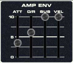
The Amp Envelope controls Polymode's voice amplitude. Like most modern poly synths, each voice (up to a maximum of 16) has its own independent envelope and associated voltage-controlled amplifier.
Vel (Velocity)- Defines how much the envelope affects amplitude via keyboard velocity. Remember that the IO Panel Poly Sources Poly Vel output is normalled to the Controls Poly Vel input, so you won't need to patch a cable to utilize amp envelope velocity. A setting of zero gives maximum dynamic range; at a setting of 10, keyboard velocity has no effect on amplitude, and is essentially full blast all the time.
Att (Attack)- Defines the length of time for VCA amplitude mod voltage to rise from minimum to maximum.
D/R (Decay/Release)- Defines the length of time for VCA amplitude mod voltage to fall from the Att stage peak to Sus stage setting (key held) or fall to zero (key released).
Sus (Sustain)- Sets the held amplitude voltage following Att and D/R phases (key held).
Resonators
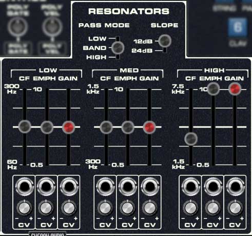
The Resonators section is one of the original instrument's most unique features. It consists of three state-variable filters in a parallel configuration. The parallel routing means the signal is split and runs into all three filters with their collective outputs summed together. Cranking up the Emph controls (aka, resonance) for each band can create three individual "peaks" or resonances, hence the "resonator" name.
Another unusual aspect of the original Resonators section is that each is band-limited. Most synthesizer filters are configured such that the cutoff frequency covers the entire audible sound spectrum (20-20,000 Hz, give or take), whereas each of the three resonators cover a "slice" of the audio spectrum, i.e. low, med, and high frequencies as follows:
Low: 60 - 300 Hz
Med: 300 - 1500 Hz
High: 1500 - 7500 Hz
The original Resonators section has two major shortcomings: the filter slopes are a little too shallow to create really dramatic resonance effects, and the cutoff frequencies aren't CV controllable. We've addressed both of these issues with a 12/24 db slope selector, as well as bipolar CV inputs for each cutoff frequency
The Resonators section excels at creating formant-type sounds, and is also great at emulating phaser-type sounds when its cutoff frequencies are swept via CV modulation.
Pass Mode - Globally selects the behavior of all three filters. Lowpass mode allows frequencies below the cutoff frequency setting to pass through, Highpass mode allows frequencies above the cutoff frequency setting to pass through, and Bandpass mode combines both lowpass and highpass modes, leaving sound only "in the middle." The cutoff frequency lies roughly halfway between the falloff slope on each side.
Slope- The nature of how a filter works is that frequencies "fall off" above or below the cutoff frequency. Slope adjusts the steepness of this falloff, hence the "slope" terminology. A 12db per/octave filter has a shallower slope, giving it a clearer and brighter character, whereas a 24db per/octave filter's steeper slope gives it a tighter and darker tone and far more pronounced ringing characteristic when the Emph slider is turned up.
Since the controls for the Low, Med, and High sections are the same other than frequency range, we'll explain them once:
CF (Cutoff Frequency)- Sets the frequency where attenuation begins. Attenuation will be above or below this frequency (or both) depending on the Pass Mode switch setting. The CV jack and attenuator beneath the slider allow positive or inverted voltage control of cutoff frequency.
Emph (Resonance)- Emphasizes sound energy at and around the current cutoff frequency by adding feedback from the filter's output back to its input. At lower settings, this can be used to create mild resonances such as those heard in acoustic instruments. At more extreme settings, resonance can create a pure sine wave at its own frequency (variable via the CF slider). Be careful with the Emph sliders as they can get loud at extreme settings (you can easily control this using each section's Gain slider). Note that this "ringing" resonant frequency is much more prominent with the Slope switch in the 24db position. The CV jack and attenuator beneath the slider allow positive or inverted voltage control of emphasis amount.
Gain- This acts as a volume control for each resonator section. Resonator sections can be muted by setting their Gain control to 0%. The CV jack and attenuator beneath the slider allow positive or inverted voltage control of gain.
VCF
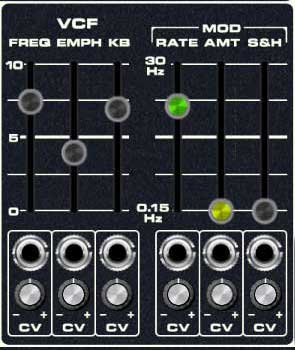
This is a standard 24db per/octave voltage-controlled lowpass filter along with a dedicated envelope generator for cutoff frequency control. Being a lowpass filter, it removes high frequencies as its cutoff frequency setting is decreased from max. Note that this is a single filter for all voices, sometimes referred to as a "paraphonic" implementation. This means that it's global for all notes, and the VCF envelope will retrigger any time a new note is played. This isn't so great for piano, clav, or other percussive sounds, but it's not too much of an issue for sustained pad, string, or organ-type sounds. The VCF and VCF Envelope controls are as follows:
Frequency - Sets the frequency where high-frequency attenuation begins. The CV jack and attenuator beneath the slider allow positive or inverted voltage control of cutoff frequency.
A note about max cutoff frequency: If the cutoff frequency is open all the way, the sound still won't be at full brightness; in other words, some high frequencies are still attenuated. Full filter brightness can be achieved by using the VCF Envelope (detailed in the next section), or by adding CV from the a mod source via the cutoff frequency CV jack. This was done to accurately emulate the behavior of the instrument's VCF - in fact, a lot of vintage analog synths work this way.
Emph (Resonance)- Emphasizes sound energy at and around the current cutoff frequency by adding feedback from the filter's output back to its input. Useful for typical synth "wah" sounds. The CV jack and attenuator beneath the slider allow positive or inverted voltage control of resonance amount.
Mod - Rate/Amount - The VCF section includes an independent triangle-wave LFO that's hard-wired to frequency modulation. The Rate slider controls LFO speed, and the Amount slider controls LFO depth. The CV jacks and attenuators beneath the sliders allow positive or inverted voltage control of the slider amounts.
Mod - S&H (Sample and Hold) - Applies sample and hold (aka, random) modulation to the cutoff frequency. The sample and hold rate is controlled by the same clock as the triangle-wave LFO above, thus its rate is set with the same Rate control. The triangle-wave LFO and S&H can simultaneously modulate the cutoff frequency as desired. The CV jacks and attenuators beneath the sliders allow positive or inverted voltage control of the slider amounts.
VCF Envelope
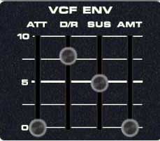
The VCF Envelope exclusively controls the VCF described above. Its controls are as follow:
Amt (Amount)- Defines the depth of envelope control of VCF cutoff. A setting of 0 has no effect on cutoff frequency; a setting of 10 would be maximum control.
Att (Attack)- Defines the length of time for VCF cutoff mod voltage to rise from minimum to maximum.
D/R (Decay/Release)- Defines the length of time for VCF cutoff mod voltage to fall from the Att stage peak to Sus stage setting (key held) or fall to zero (key released).
Sus (Sustain)- Sets the held VCF cutoff mod voltage following Att and D/R phases (key held).
Mode Filters
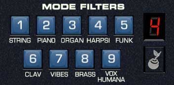
On the original instrument, these buttons allowed selection of hard-wired sound presets; in addition to changing waveform, octave, and envelope parameters, the numbered preset buttons also routed audio through fixed filter circuits. Each preset had its own custom fixed filter board, known as a "mode filter." Unlike a typical synth filter, they have no external controls and they aren't voltage controllable, so they can't change timbre over time. It's best to think of the Mode Filters as preset EQ curves.
Given Voltage Modular's sophisticated factory and user preset browser, we felt it would be redundant (and potentially confusing) for the Mode preset buttons to affect all of Polymode's controls, so please keep in mind that the Mode filter names refer only to the mode filters themselves, not entire sound patches (the entire factory presets are accurately reproduced and appear as the first nine presets in the standard Voltage Modular Polymode Presets bank).
There were actually two original models - the 203A, which is the full-tilt boogie version with numerous controls, and eight sound presets/mode filters. A couple of years later, a less expensive, cut-down version (model 280a) was released., but it increased the number of presets (and mode filters) to 14. Generally speaking, the 280A is less desirable, but it featured the aforementioned "Vox Humana" preset, made famous by new wave icon, Gary Numan. As a result, many 203A owners have their instruments modified to eliminate one of the lesser presets and replace it with the Vox Humana settings and mode filter PCB. We've essentially done this in the Polymode module - it retains all eight of the standard mode filter presets and adds Vox Humana as a ninth "extra" preset.
To use the Mode filters, simply select one and raise the Mode slider in the Master Gain section. The LED numeric indicator displays the currently selected mode filter. As mentioned, switching mode filters won't affect other parameters.
Master Gain (Mixer)
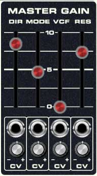
The Master Gain section is where all Polymode signals are mixed.
Dir (Direct)- Sets Direct signal output amount. This signal is the combination of both oscillator ranks, following the Rank Mix slider and prior to any of the filters.
Mode- Sets the Mode Filters output level. The CV jack and attenuator beneath the slider allow positive or inverted voltage control of Mode Filter level.
VCF- Sets the VCF output level. The CV jack and attenuator beneath the slider allow positive or inverted voltage control of VCF level.
Res (Resonators)- Sets the Resonators output level. The CV jack and attenuator beneath the slider allow positive or inverted voltage control of Resonators level.
Outputs
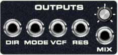
From the Master Gain section, signals travel to the Outputs section. The Mode, VCF, and Resonators individual output levels are affected by Master Gain mixer levels.
Dir (Direct)- This signal is the combination of both oscillator ranks, following the Rank Mix slider and prior to any of the filters.
Mode- Mode Filters direct out.
VCF- VCF direct out.
Res (Resonators)- Resonators direct out.
Mix and Volume knob- This the master summed output from the Master Gain mix. The master mix level is set with the volume knob above the jack.