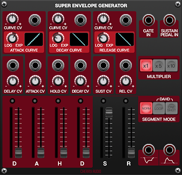
Cherry Audio’s Super Envelope Generator is the dream-come-true envelope for modular synthesists. It starts with a complex DAHDSR envelope (Delay-Attack-Hold-Decay-Sustain-Release). The shapes of the Attack, Decay, and Release stages are individually controllable, morphing from logarithmic to linear to exponential, and these shapes can all be modulated via control voltage. On top of that, the length of each stage (and the sustain level) is CV-controllable as well! Powerful visual feedback is provided every step of the way, so you can see at a glance what's happening with your envelope generator in real-time.
We are going to assume that you understand how a standard ADSR envelope works. If you are unfamiliar with envelopes in general or need a recap, please check out the documentation for the standard Envelope Generator which goes over the basics in detail.
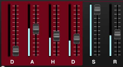
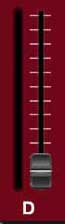
DAHDSR Sliders
"D" (Delay) slider- This is the first stage of the envelope and defines the length of time (after receiving a gate signal) the envelope will remain at 0V before starting the Attack phase.
"A" (Attack) slider- Defines the length of time it takes for voltage to rise from 0V to 5V.
“H" (Hold) slider- Defines how long the envelope will remain at 5V before starting the envelope’s Decay phase.
"S" (Sustain) slider- Sets the held voltage level (sustain level) following the Decay phase.
"R" (Release) slider- Defines the length of time for voltage to fall from Sustain level to 0V when the gate is released.
LED stage indicators- These illuminate to show the currently active envelope stage.
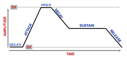
Below is a diagram of a DAHDSR envelope to help clarify the individual stages.
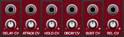
Each of the DAHDSR sliders can be CV-controlled using their respective CV input jack and bipolar attenuator. When controlling a slider’s value externally, the light blue LED meter to the left of each slider shows the modulation in real time.
It is important to understand that the sliders themselves only show the initial value before any modulation. The blue LED meter displays the actual current setting being used for each stage of the envelope.
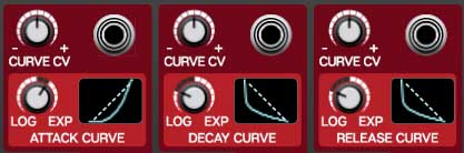
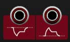
Attack, Decay, and Release Curves
The shape, or curve, of the Attack, Decay, and Release stages of the envelope can be adjusted individually. Each stage has its own curve control which can morph smoothly from logarithmic, to linear, to exponential.
A logarithmic curve will move quickly at first, then slower as it approaches its destination (as shown in the Decay and Release Curve displays above).
A linear curve moves towards the destination voltage at a constant pace.
An exponential curve will move slowly at first, then quickly “ramp up” as it approaches its destination (as shown in the Attack Curve display above).
The shape of each curve can be CV-controlled using its respective Curve CV jack and bipolar attenuator and all modulations will be visually displayed in real time.
Input
Gate In jack- A gate signal received at this jack triggers the envelope to start when in Normal or One Shot mode.
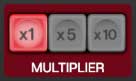
Multiplier
These buttons multiply all of the slider’s timed values by one, five, or ten making it possible to have seriously long envelope shapes! As an example, if the Decay slider is set to 1000ms (1 second) with the x1 button selected, the decay length will be 5 seconds or 10 seconds with the x5 or x10 buttons selected respectively.
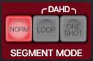
Segment Mode
The Super Envelope Generator can be used in three different modes.
Norm- This is the normal envelope behavior where when a gate signal is received, the envelope starts at the Delay stage, moves to the Attack, Hold and Decay stages, sustains at the Sustain level, then starts the Release stage when the gate stops.
Loop- Pressing this button loops the first four stages (DAHD) continuously making the envelope behave more like an LFO. As soon as the button is pressed, the envelope starts at the Delay stage, moves to the Attack, Hold and Decay stages, then loops back to the Delay stage to start over again. The Sustain and Release stages are not used at all in this mode, therefore the Decay stage will always return to 0V before looping back to the beginning.
One Shot- This mode also only uses the first four stages (DAHD) of the envelope. Each time a gate signal is received at the Gate In jack, the envelope starts at the Delay stage, moves to the Attack, Hold and Decay stages and then stops. All four stages will be completed regardless of how long the gate signal is held. Note that since the Sustain stage is inactive, the Decay stage returns all the way back to 0V.
Outputs
Env Out and Env Out Inv- These are the envelope poly voltage outputs. The jack on the right has a positive voltage output of 0V to +5V; the jack on the left has an inverted negative voltage output of 0V to -5V.