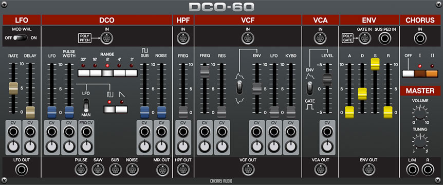
The DCO-60 module is a fully self-contained polyphonic synth that models every aspect of the beloved classic Juno-106 synthesizer, from its self-oscillating filter to its dreamy chorus effect. In addition, it’s loaded with patch points and mod inputs that immensely expand its flexibility and allow individual sections to be freely combined with other Voltage modules.
Patch Cord Normalling
IO Panel Normalling
DCO-106 takes advantage of Voltage Modular 2.0’s patch cord normalling feature. This allows modules to be coded to communicate directly with IO Panel connections without the use of patch cords via “invisible” patch cords. The idea is to speed up setup by automatically configuring often-used cables and routings.
In the case of DCO-106, this means the IO Panel Poly Pitch and Poly Gate outputs are normalled to DCO-60’s DCO Poly Pitch and ENV Poly Gate jacks, respectively. In practice, this means that the only cables that need patching to play a new instance of DCO-60 are one or both of the Master output jacks (which get patched to one or more of the IO Panel Out To Host jacks).
If a patch cord from another module is plugged into the DCO Poly Pitch or ENV Poly Gate jacks, the normalled, “invisible” cable is overridden, thus eliminating the IO panel connection. If you’d like to maintain the connection from the IO Panel, simply patch a cable from the IO Panel output as usual, in addition to the connection from a module as shown below.
The LFO section of DCO-106 can optionally take advantage of a normalled IO Panel connection as well (from the Mod Wheel output); we’ll discuss this in the LFO section.
Internal Normalling
DCO-106 also makes use of a number of internally normalled connections. Looking at the DCO-106 panel, you’ll notice that its sections have the appearance of multiple modules, with inputs at the top and outputs at the bottom. If these sections were standard Voltage modules, you’d need to patch each of them together appropriately to hear sound. (i.e. oscillator output to filter input, filter input to amplifier, etc.) In the DCO-106 module, all of these sections use normalled connections “under the hood,” making it function like a conventional hard-wired standalone synthesizer. But as described above, normalled connections can be overridden by simply plugging cables into the jacks.
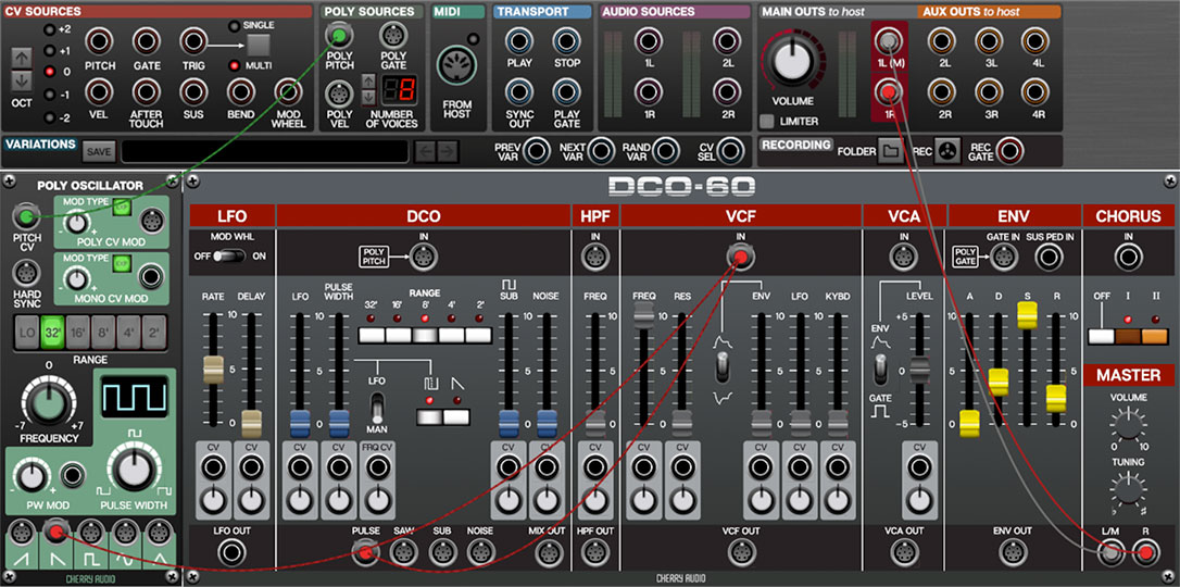
For example, to add a second poly oscillator, you would patch a cable from the IO Panel Poly Pitch out to a Poly Oscillator, then patch its output to DCO-106’s HPF or VCF input. Because plugging into a normalled jack overrides the existing normalled connection (in this case the DCO output), a cable needs to be patched from one of the DCO outputs to the filter input, as shown in the image above. For finer control of oscillator balance, the external oscillator and DCO-106 oscillator could be routed through a poly mixer module prior to the filter input.
One important thing to keep in mind is that normalled input jacks are overridden when a cable is plugged into them, but normalled output jacks are not. Because of this, in the example above, it isn’t necessary to patch a cable from the IO Panel Poly Pitch out to DCO-106’s DCO Poly Pitch In jack to maintain the IO Panel to DCO connection. In other words, normalled outputs behave as if they’re multed to more than one destination.
LFO Section
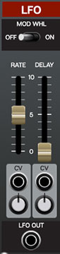
The low-frequency oscillator (LFO) is creates a sub-audio range triangle wave intended for modulation purposes.
Mod Wheel Switch- This is a handy, but potentially confusing feature, so don’t skim this section. If the switch is in the Off position, the LFO is always “on.” Its effect is immediately audible by moving the LFO sliders in the DCO and VCF sections. Moving the switch to the On position activates a normalled connection from the IO Panel CV Sources Mod Wheel jack, and enables control of LFO depth with an external keyboard controller mod wheel. If the mod wheel is all the way down, LFO depth is zero. This makes setting up a mod wheel to add vibrato or wah effects very easy.
Rate- Sets the LFO rate from 0.1 to 30 Hz. The rate can be CV controlled with the CV jack and attenuator beneath the slider.
Delay- Moving this slider up gradually delays the onset of LFO depth. The delay time can be set from 0 to 5 seconds. Because DCO-60 includes separate LFO’s for each polyphonic voice, onset delay is independent for each note, which is a nice effect when playing melodies or arpeggiated note passages. The delay time can be CV controlled with the CV jack and attenuator beneath the slider. LFO Delay time can be CV controlled with the CV jack and attenuator beneath the slider. The bipolar attenuator knob’s center position is zero; turning it to the right adds positive mod, and turning it to left adds negative mod.
When the Mod Whl switch is in the on position, the Delay slider “grays out” and is disabled (because you wouldn’t want the onset of LFO mod delayed when controlling mod amount with a mod wheel).
LFO Out jack- The original Juno synths included hard-wired routings along with attenuation sliders to the DCO and VCF sections. This is replicated in DCO-60, but the LFO section may be used as a mod source for any of DCO-60’s mod inputs by patching the LFO Out jack to any mod input (even external modules).
DCO Section
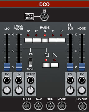
DCO-60 accurately models the unique master clock and divider architecture used in the original Juno synth oscillators.
Poly Pitch In CV jack- Accepts a CV input for pitch. This is normalled from the IO Panel Poly Sources Poly Pitch jack, so in most situations, no connection will be necessary. This input is useful if you’d like to patch in a sequencer or other pitch control source. And like all jacks in Voltage 2.0, it’s actually a mult input with unlimited connections, so multiple inputs can be patched in.
Range- Sets the basic pitch range of the oscillator, displayed in traditional organ footage.
Wave Select buttons- These allow selection of sawtooth, pulse, or both waves simultaneously.
Pulse Width and LFO/Manual Switch-
Man position- The Pulse Width slider sets the width or "duty-cycle" of the pulse wave. Setting the slider to zero outputs a perfect square wave, i.e. 50% duty-cycle. Moving the slider upward narrows its pulse width as well as the thickness of sound until it almost disappears.
LFO position- Pulse width is modulated by the onboard LFO (often abbreviated to PWM). The modulation depth is set by the Pulse Width slider, and the rate is defined by the LFO section Rate slider.
In either switch position, the Pulse Width slider can be CV controlled with the CV jack and attenuator beneath the slider.
LFO slider- Adds frequency modulation from the hard-wired low-frequency oscillator section immediately to the left of the DCO. The LFO slider amount can be CV controlled with the CV jack and attenuator beneath the slider.
Sub slider- Adds a square wave one octave beneath the current range selection, useful for adding girth to oscillator tones. The Sub slider level can be CV controlled with the CV jack and attenuator beneath the slider.
Noise slider- Sets the level of the white noise generator. Both oscillator wave buttons can be disabled if white noise only is desired. The white noise level can be CV controlled with the CV jack and attenuator beneath the slider.
Waveform Individual and Mix Poly Output Jacks- Individual outs jacks for pulse, saw, sub oscillator, noise, and DCO mix output. Sub oscillator and noise outputs are not affected by their corresponding sliders and CV control in the individual outputs, but they will be affected in the Mix Out jack.
HPF Section
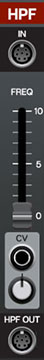
A highpass filter removes low frequencies as its cutoff frequency setting is increased, resulting in a thinning out of sound. The highpass filter section in the original Juno synths is a simple, non voltage-controlled affair, and acts more like a thickness control than a full-fledged filter. DCO-60 adds a CV input and attenuator, enabling voltage control.
In jack- The HPF poly In jack is normalled from the DCO Mix Out, so in most situations, no connection will be necessary. This input is useful if you’d like to patch sounds in from additional modules. Remember that connections will override the normalled signal from the the DCO; if you’d like to augment the standard DCO with additional sound sources, simply patch a cable from the desired DCO output to the HPF In jack along with any other poly audio sources.
Freq- Sets the frequency where low-frequency attenuation begins. The CV jack and attenuator beneath the slider allow voltage control of its setting.
Out jack- Output of the highpass section. This is normalled to the lowpass filter (VCF) input, so in most cases, it won’t be needed.
VCF Section
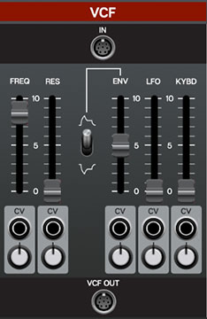
The VCF section is a 24 db/oct lowpass filter that removes high frequencies as its cutoff frequency setting is decreased from max, resulting in a dulling of sound. DCO-60 features a super-accurate emulation and adds a CV input and attenuator for extensive voltage control.
In jack- The poly In jack is normalled from the HFP Out, so in most situations, no connection will be necessary. This input is useful if you’d like to patch sounds in from additional modules.
Freq- Sets the frequency where high-frequency attenuation begins. The CV jack and attenuator beneath the slider allow voltage control of its setting.
Res- Short for “resonance,” this emphasizes sound energy at and around the current cutoff frequency by adding feedback from the filter's output back to its input. At lower settings, this can be used to create mild resonances such as those heard in acoustic instruments. DCO-60’s implementation is fully self-oscillating - at extreme settings, it can be used as a sine wave generator, but be careful because high resonance settings can result in loud, screamy, dog-terrifying (and speaker blowing) occurrences. The CV jack and attenuator beneath the slider enable voltage control of its amount.
Env Slider and Mod Invert Switch- The Env slider sets the amount of envelope modulation applied from the envelope generator. With the invert switch in the up position, envelope affects the cutoff frequency positively. In the down position, envelope mod is inverted for “reverse” effects. The Env slider amount can be CV controlled with the CV jack and attenuator beneath the slider.
LFO- Adds cutoff frequency modulation from the onboard low-frequency oscillator section. The LFO slider amount can be CV controlled with the CV jack and attenuator beneath the slider.
KYBD- This is short for “keyboard” and causes the cutoff frequency to increase as ascending notes are played on a keyboard. The idea behind this is, because actual note frequencies rise as higher pitches are played, the Kybd slider adds a rising CV to the cutoff frequency in order to maintain the brightness of notes as higher pitches are played. The Kybd slider amount can be CV controlled with the CV jack and attenuator beneath the slider.
VCA Section
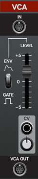
VCA is short for “voltage-controlled amplifier,” and for all intents and purposes, you can think of it as an automated, polyphonic volume knob.
In jack- The poly In jack is normalled from the VCF Out, so in most situations, no connection will be necessary. This input is useful if you’d like to patch sounds in from additional modules.
Level- In the original Juno synths, its main purpose was to act as a master volume control, in order to balance volume levels between presets. Voltage Modular allows volume adjustment in a number of different ways, so its importance isn’t as significant here, but we’ve replicated it as with the original. Typically this gets set to the center zero setting, and volume can be added or subtracted by moving it up or down. The Level slider amount can be CV controlled with the CV jack and attenuator beneath the slider, which can be useful for tremolo effects or wild amplitude modulation effects if the mod source is an audio-rate oscillator.
Env/Gate Switch- The original Juno synths included a single envelope generator that had to perform double-duty, applying to the lowpass filter as well as the VCA sections. In order to add some flexibility, the Env/Gate switch effectively disconnects the envelope generator from the VCA.
If the Env/Gate switch is in the Env (up) position, the envelope generator affects amplitude (VCA) and filter cutoff (if the the VCF Env slider is up) simultaneously. If the switch is in the down Gate (down) position, the envelope generator still affects filter cutoff, but note amplitude will instantly turn on and off, like an organ.
VCA Out- Output of the VCA section. This is normalled to the Chorus section input, so in most cases, it won’t be needed.
ENV Section
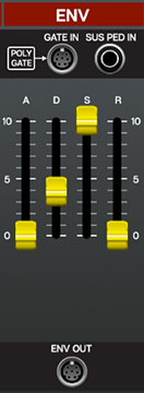
The envelope generator section is a standard ADSR envelope generator used to shape amplitude curves and/or filter CV (or other stuff, if the Env Out jack is sued). If you're not familiar with the operation of envelope generators, here's an overview:
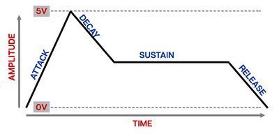
When a gate voltage is sent either from the normalled IO Panel Poly Gate jack or from another source into the Gate In jack, the envelope generator outputs a dynamically changing voltage, according to the settings of its four stages. The Attack stage defines how long it takes for the output voltage to rise from 0 to 5 volts. Once the attack stage reaches 5V, it moves to the Decay phase, which defines how long it takes to fall from 5V to the setting of the Sustain phase. Unlike the Attack, Decay, and Release phases, which define times, Sustain simply sets the held voltage level following the Attack and Decay phases - this usually equates to the envelope output level while holding down a key on a keyboard controller. Finally, the Release knob defines the the length of time it takes for the voltage to fall back to 0V when the gate input voltage is removed, i.e. when the key is released (hence the clever name).
"A" (Attack) slider- Defines the length of time for voltage to rise from 0V to 5V when the gate voltage is applied.
"D" (Decay) slider- Defines the length of time for voltage to fall from the attack stage 5V peak to Sustain stage setting.
"S" (Sustain) slider- Sets the held voltage level following attack and decay phases.
"R" (Release) slider- Defines the length of time for voltage to fall from sustain level to 0V when a key is released.
Env Out- Output of the VCA section. This is normalled to the VCA input and VCF Env slider, so in most cases, it won’t be needed.
Chorus Section
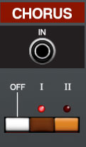
DCO-60’s Chorus section beautifully replicates the renowned, lush Juno-style stereo chorus.
Off, I, II buttons- These set the amount of chorus effect. Off is uh… off. The I and II positions are very similar, but the mod speed is slightly faster in the II position. Activating I and II at the same time results in a much faster, mono chorus sound.
Master Section
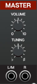
Volume- Sets DCO-106 master volume.
Tuning- Sets master tuning up or down by a half-step.