The Cherry Audio Analog Shift Register is an eight-stage analog-style shift register that can be triggered via an internal or external clock source.
The concept behind an analog shift register (ASR) is similar to a sample and hold module which repetitively “samples” an input signal and outputs its voltage until triggered again. In fact the first output of the Analog Shift Register is exactly the same as the Sample and Hold module. What makes the ASR different is that every time a new sample is taken, the previous sample is “shifted” sequentially to the next output.
Typically the outputs are used to control the pitch of individual oscillators to create a canonic melody or pattern where the leading oscillator voice is “followed” by multiple subsequent voices.
Inputs, Outputs and Controls
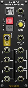
Input jack + normalled white noise generator- This is the input jack for the audio or control signal to be sampled. If nothing is plugged in, it receives white noise from the internal white noise generator. Plugging a jack in overrides the normalled noise source.
Ext Trigger jack- A 5V pulse or gate received at this jack will externally trigger the module.
Internal Clock Out jack- If internal clock is selected, this allows to be used to trigger additional destinations, and allows the Analog Shift Register to function as a master clock source.
Trigger Source- The buttons Int and Ext select between the internal and external trigger source.
Rate- Controls the rate of the internal trigger source from 0.02 Hz - 50 Hz.
1-8 output jacks- These are the jacks where the sampled voltages will be output. Each sampled CV will initially be available at the first output and shifted sequentially to the next output with each following trigger. Note that voltages from the eighth output are not shifted back to the first output.