Poly EG Station features eight fully independent ADSR envelope generators. Though it's intended for use with the Cherry Audio FM Station oscillator module, it can be used with any modules in Voltage. It packs a lot of envelopes into a relatively compact footprint and features velocity CV inputs allowing control of envelope intensity. Other polyphonic capabilities and jacks, it's essentially identical to the "mono" EG Station module.
How ADSR Envelope Generators Work
If you're not familiar with the operation of standard envelope generators, here's how they work: when a gate voltage is sent to one of the Gate jacks, the envelope generator outputs a voltage that changes dynamically according to its four stage settings.
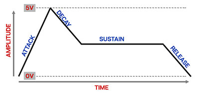
The Attack stage defines how long it takes for the output voltage to rise from 0 to 5 volts. Once the attack stage reaches 5V, it moves to the Decay phase, which defines how long it takes to fall from 5V to the setting of the Sustain phase. Unlike the Attack, Decay, and Release phases, each of which define a time, Sustain sets the held voltage level following the Attack and Decay phases - this usually equates to the envelope output level while holding down a key on a keyboard controller. Finally, the Release knob defines the the length of time it takes for the voltage to fall back to 0V when the gate input voltage is removed (typically when you let go of a key on a keyboard controller).
Inputs, Outputs, and Controls
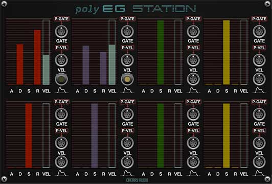
Control Bars and CV Indicator Bars
EG Station's main controls are a bit of a departure from other Cherry Audio modules. Instead of standard knobs or sliders, its main controls are colored illuminated bars. These work just like the slider controls in other modules. To change values, grab the control bar at its top edge and move it or click anywhere in the control travel to jump to the setting (this is helpful when the control is set to minimum; you won't have to precisely click the tiny visible region of the bar). Hovering the mouse on a control bar causes it to light up. The controls bars behave the same as any standard Voltage slider control- right-clicking them allows all standard operations including Perform and MIDI controller assignments.
The control bars are color-coded to match the FM Station module's four operator sections, but otherwise each of the envelopes are functionally identical.
P-Gate jacks (normalled)- P-Gate is short for poly gate. This is where you'll patch gate voltages to initiate an envelope generator cycle. The connection from the IO Panel Poly Sources Poly Gate CV out is semi-normalled to all eight of EG Station's P-Gate inputs - in other words, even though there are no visible cables, it's automatically connected "under the hood." We think you'll find this makes using Poly EG Station really fast and easy - it also dramatically reduces cable clutter.
If a cable or a cable bus is connected to a P-Gate input jack, the IO Panel connection is overridden for that jack (i.e., disconnected). This is useful if you don't want to use the IO Panel Gate jack output when using an alternate poly gate source.
Can I use a "trigger" to trigger an envelope generator? It would seem logical, but the answer is, "sometimes, but generally, no." First let's clarify the difference between a gate signal and a trigger signal:
A gate is a constant voltage. If you're playing a keyboard, it remains high (i.e. +5V) as long as the key is held down.
A trigger is a rapid spike of +5V. It's useful for a number of things (like turning stuff on and off, or triggering "one-shot" drum sounds or modules).
With this in mind, Poly EG Station needs to see a constant gate voltage to move through the Attack and Decay phases and hold during the Sustain phase. Removing the gate voltage following the Sustain phase tells it to move to the Release stage. Conversely, using a trigger signal will cause the envelope generator to immediately jump to the Release phase.
P-Vel jacks (normalled)- P-Vel is short for poly velocity. These poly CV in jacks allow the overall voltage output of the envelope to be controller via CV. Like the P-Gate jacks, all eight P-Vel CV inputs are semi-normalled to the IO Panel Poly Vel CV outputs, so they don't need to be patched to function. The IO panel connections can be individually overridden by plugging poly cables into them. Poly velocity CV intensity is controlled by the Vel control bar.
Poly Envelope Outs - The envelope voltage outputs have an envelope icon beneath them. Their output voltage ranges from 0V to +5V.
"A" (Attack) control bar- Defines the length of time for voltage to rise from 0V to 5V when the gate voltage is applied.
"D" (Decay) control bar- Defines the length of time for voltage to fall from the Attack stage 5V peak to Sustain stage setting.
"S" (Sustain) control bar- Sets the held voltage level following Attack and Decay phases.
"R" (Release) control bar- Defines the length of time for voltage to fall from Sustain level to 0V when gate is released.
Velocity control bar- This an attenuator controlling the intensity of CV from the Vel poly CV jack. Moving the bar up from middle position adds positive CV input.
This Velocity bar also displays an unfilled rectangle that displays incoming the sum total of incoming velocity CV's in real-time.
The A, D, S, and R control bars illuminate when the mouse is hovering over them.