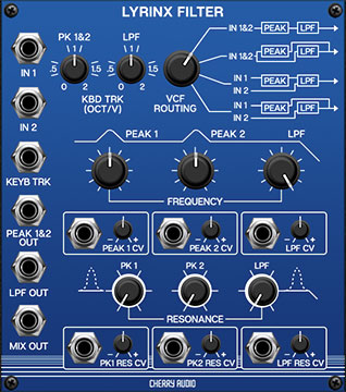
The Lyrinx Filter precisely replicates the unique Voltage-Controlled Formant Filter of the super rare Synton Syrinx synthesizer. Consisting of two "peak" (bandpass) and one lowpass filter with multiple routing configurations, its excels at creating unique vocal-like timbres and includes extensive CV capabilities. This lets you easily create funky "talking" synth sounds. Lyrinx is super easy to use and capable of a wide array of timbres.
As mentioned, Lyrinx includes two "peak" (bandpass) filters and one lowpass filter. The two peak filters and one lowpass filter can be arranged in a few different ways dependent on the VCF Routing selector knob setting, but generally speaking, the signal flows from left to right going to the peak filters first, then to the lowpass filter.
How Bandpass and Lowpass Filters Work
For those unfamiliar with how different filter types work, let's review how bandpass and lowpass filters affect audio signals:
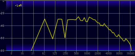
The original Syton Syrinx filter features two "peak" filters; as mentioned these are the same as bandpass filters. A bandpass filter is actually a combination of a lowpass filter and a highpass filter, configured in series (signal goes through one, then the other). The lowpass section blocks frequencies below the cutoff frequency setting, but allows frequencies above the cutoff frequency to pass through. The highpass section does the opposite: it blocks frequencies above the cutoff frequency setting, but allows frequencies below the cutoff frequency to pass through.
The result is that only a "slice" of frequencies below and above the cutoff frequency are allowed to pass through. However, this slice has to be relatively wide, otherwise very little sound energy would remain audible. The plot above shows how a bandpass filter affects an audio signal. (The vertical axis represents amplitude and the horizontal axis represents frequency.)
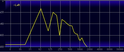
A lowpass filter allows frequencies below the cutoff frequency setting to pass through, but blocks frequencies above the cutoff frequency. The frequency plot above shows the effect of a lowpass filter on a saw wave. Notice how the high-frequency content trails off at the top of the audio spectrum.
Inputs, Outputs and Controls
The Lyrinx Filter contains a semi-terrifying quantity of controls, but it's actually pretty easy to use. Let's go over their functions.
In 1 and In 2 jacks- Lyrinx Filter features two individual inputs that allow a great deal of flexibility dependent upon the setting of the VCF Routing knob. In the first two positions, both inputs signals are mixed equally to one mono signal, so hey, free mixer. In the third and fourth positions, the two inputs are separately routed through the peak and lowpass filters (more on this in VCF Routing control section).
Keyb Track CV jack- This is a CV input, intended for use with the IO Panel Pitch CV output jack (though any CV source can be plugged into it). It allows cutoff frequencies to increase as higher notes are played on a keyboard or sequencer. The idea is to allow the harmonics of a sound to remain constant as higher notes are played. The Keyb Track input works in conjunction with the Kbd Trk knobs, which act as CV amount attenuators/boosters.
Peak 1&2 Out- Individual output jack for both peak filters.
LPF Out- Individual output jack for lowpass filter. Depending on which input is used and the position of the VCF Routing selector, this may or may not be affected by the peak filters (sometimes making it the same signal as the Mix Out jack).
Mix Out- Output signal of all filter sections mixed together, in accordance with the VCF Routing signal flow diagram.
Kbd Trk (Oct/V) Pk 1&2 and LPF- These act as attenuators or boosters in conjunction with the the Keyb Trk CV input jack. Pk 1&2 affects the cutoff frequency for both peak filters, while LPF affects the lowpass filter's cutoff frequency.
At a setting of 1 (i.e. 100%), this allows a sound's harmonics to remain constant (i.e., not become duller) as higher notes are played. The Synton Syrinx is unique in that its keyboard tracking controls go up to "2," equivalent to a setting of 200%. This allows far more contrast in filter brightness from low to to high notes than typical synth filters.
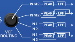
VCF Routing- This selector switch allows four different routings through the bandpass and lowpass filters for different tonal colors. The front panel legend makes the signal flow easy to visualize.
Position 1- In 1 and In 2 are equally mixed, then routed through peak filters and lowpass filter in series. In 1 or In 2 can be used if a single signal is being processed.
Position 2- In 1 and In 2 are equally mixed, then the signal is multed and separately routed through the peak filters and the lowpass filter. In 1 or In 2 can be used if a single signal is being processed.
Position 3- In 1 is routed through the peak filters and the lowpass filter in series. In 2 is routed through the lowpass filter only.
Position 4- In 1 is routed through the peak filters only. In 2 is routed through the lowpass filter only.
Frequency- Sets the frequency where attenuation begins. Attenuation occurs above and below the cutoff frequency for the peak filters, and only above the cutoff frequency for the LPF (lowpass filter).
Peak 1 CV, Peak 2 CV, LPF CV mod inputs/attenuators- Adjusts the depth of the cutoff frequency modulation, i.e. how much the filters sweep back and forth when a CV signal is applied. The attenuators allow negative or positive CV control of cutoff frequency. The center setting correlates to no modulation.
Resonance Pk1, Pk2, and LPF- Emphasizes sound energy at and around the current cutoff frequency by adding feedback from the filter's output back to its input. At lower settings, this can be used to create mild resonances such as those heard in acoustic instruments. At more extreme settings, resonance can create a pure sine wave at its own frequency. Be careful with the Resonance sliders as they can get loud at extreme settings.
Note that subtle (or not so subtle) use of the individual Resonance controls is the key to creating unique "talking" filter effects (along with cutoff frequency CV mod).
Pk1 Res CV, Pk2 Res CV, LPF Res CV mod inputs/attenuators- Adjusts the depth of resonance modulation. The attenuators allow negative or positive CV control of resonance level. The center setting correlates to no modulation.