The Binary module is a dual module that continuously tests an incoming audio or control signal to determine if its voltage is greater than zero (> 0) or less than zero (< 0) and outputs a selected voltage whenever the condition is true. The output will always be a binary signal, meaning it is either on (outputting the selected voltage) or off. It basically creates a series of gate signals which can be used to turn things on and off, trigger envelopes, step through sequencers etc.
One of the coolest things about modular synthesis and Voltage Modular is the ability to create unique relationships between modules so that they “react” to one another. The Binary module can “automatically” trigger an event or action based on other signals already present within a patch. It could be used, for example, to send only higher notes of an arpeggiator to a reverb send or change a drum sequencer’s pattern every time an LFO passes zero.
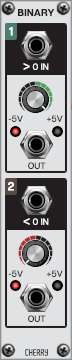
Inputs, Outputs and Controls
> 0 and < 0 In jacks- Input jack for the audio or control signal whose voltage will be tested. The top module tests whether or not the signal is above zero and the bottom module tests whether or not it is below zero.
Pro Tip: A DC Source module can be used to offset the input signal’s voltage making it possible to test if a signal is above or below voltages other than zero.
-5V to +5V and LEDs- This knob selects the voltage that will be output any time the tested condition is true. The green LED shows that the condition is true while the red LED indicates that it is false.
Out jack- Output jack for the binary signal created. If both modules are testing the same input signal, the outputs will alternate outputting voltage and can be combined to create a square wave made up of both selected voltages.