Panner
Percussion EG
Plug-In Host
Poly Amplifier
Poly CV Converter
Poly Filter
Poly Glide
Poly Multiple
Poly Octave Oscillator
Poly Oscillator
Poly Six-Input Mixer
Poly Stereo Spread
Poly To Mono
Poly Unison
Phaser
Poly EG-20
Poly EG Station
Poly Envelope Generator
Poly FM Station
Poly Quantizer
Poly Synthesizer Expander Module
Poly Super Envelope Generator
Poly VCF-20 Filter
Poly VCO-20 Dual Oscillator
Polymode
AirWave Vector Oscillator
Drum Oscillator
LFO
Noise Generator
Oscillator
Poly Octave Oscillator
Poly Oscillator
Sampler I
Sampler II
Sub Octave
Super LFO
Super Oscillator
TB Oscillator
Vintage Oscillator
Additive Oscillator
AirStep Oscillator
FM Station
Poly FM Station
Poly VCO-20 Dual Oscillator
VCO-20 Dual Oscillator
The Cherry Audio "standard" LFO, or low-frequency oscillator, is a multi waveform, analog-style LFO. It generates six different control voltage (CV) waveforms and is capable of audio-rate modulation.
If you are unfamiliar with using LFO's, a simple application would be to slightly modulate an oscillator’s frequency to create vibrato (pitch modulation), or to modulate a VCA’s amplitude to create a tremolo effect (amplitude modulation). Modulating the cutoff frequency of a filter can create a dubstep-style wobble, or if modulated very slowly, long sweeping tonal shifts.
Many of the Voltage Module modules have dedicated CV inputs, sometimes labeled as "mod" inputs, all of which can be modulated with the LFO. But remember, just because an input isn’t labeled as CV or mod, that doesn’t mean you can’t route an LFO to it! Patch away and see what happens- unexpected results are what makes modular synthesis so much fun.
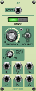
Inputs, Outputs, and Controls
Reset jack- Any trigger or gate CV greater than +2.5 volts received at this input jack will force-reset the LFO’s cycle. Connect the Trig or Gate jack in the IO Panel CV Out section to this input jack to reset the LFO each time a new note is played, or connect the Trig Out from a sequencer to keep the LFO in sync with the sequence.
Range- The L (low) and H (high) buttons alter the frequency range of the LFO. When L is selected, the LFO is a typical low frequency, or sub-audio rate, oscillator ranging from 0.02 Hz - 10 Hz. When H is selected, the LFO’s frequency range is from 5 Hz - 400 Hz, making audio rate modulation possible.
Frequency- Sets the frequency, or rate, of the LFO. Frequency values are represented in Hz, or cycles per second. In other words, 1 Hz means it takes one second to complete a full cycle of the waveform. Therefore, 2 Hz = 0.5s, 4 Hz = 0.25s etc. Don’t worry though, you don’t need to know the math because the LED beside the knob flashes to display the LFO's current frequency.
Polarity- Sets the polarity of the LFO output waveforms. In the Bi position ("bipolar," meaning above and below 0V), the LFO will output signals ranging from -5V to 5V. In the + position, the output signals will range from 0V to 5V, and in the - position, the signals will range from -5V to 0V. Note that in the + and - positions, the amplitude of the LFO has been halved, and the center point of modulation has been shifted to 2.5V or -2.5V, respectively. This can be desirable in many situations, but be cautious of using these modes with pitch modulation; if you were to create vibrato using the + mode, for example, your patch may sound great on its own, but the oscillators will actually be slightly sharp, and out of tune with the rest of the world!
Pulse Width- This knob adjusts the width, or “duty-cycle,” of the pulse wave output. At 50%, a symmetrical square wave is produced, meaning the positive and negative portions of the cycle are equal lengths. As the knob is turned clockwise, the positive portion of the LFO cycle is increased; as it is turned counter-clockwise, the positive portion of the cycle is decreased. Be aware that the knob goes all the way to 0% and 100%- at either of these extremes, the modulation will be static.
Waveform Output jacks- These are the output jacks for the LFO signals. Each jack outputs a different waveform and can be used simultaneously in any combination. Shape options are square, random (i.e. sample and hold), sine, ramp up, ramp down and triangle.