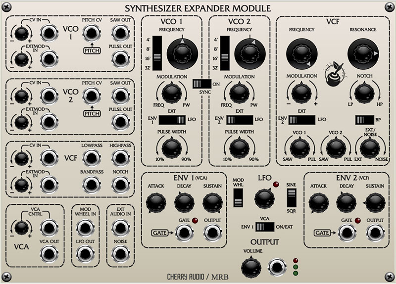
The Voltage Modular Synthesizer Expander Module is an emulation of the classic Oberheim® Synthesizer Expander Module, aka the "SEM." Originally released in 1974, the keyboardless, mono SEM module was intended as a companion to the Oberheim DS-2, one of the earliest digital sequencers. Soon thereafter, Oberheim realized they could interface a digitally scanned keyboard, mount the whole mess in a big box, and create polyphonic synthesizers, beginning with the Two Voice, followed by the Four Voice, and finally the beastly Eight Voice (be sure to check out Cherry Audio Eight Voice, our super-rad virtual instrument emulation).
Though it was a simple, barebones monosynth, the SEM sounded fantastic, and had a tone quality very different than the common fuzzy, fat Moog sound, thanks to its 12 dB/oct state-variable filter. With lowpass, bandpass, highpass and notch modes, this flexible filter was the star of the show. We've precisely recreated it here with a detailed emulation programmed by award-winning synth designer, Mark Barton (MRB).
The design is similar to the "patch panel" reissue SEM's released in the 2000's; these were basically identical to the 70s versions but added an extensive patch panel for modular synth flexibility.
Semi-Normalled Patching
The Voltage Synthesizer Expander Module would best be described as a normalled semi-modular synth. Unlike most Voltage modules, it contains standard synth sections (i.e. oscillators, filters, etc.) that are internally patched together. Additionally, the Voltage IO Panel Pitch and Gate connections are "normalled," i.e. invisibly connected to Synthesizer Expander Module's Pitch CV and Gate jacks. In fact, the only connection that needs to be made to begin playing is the Output jack to the IO Panel Main Outs To Host.
Any cables patched to the normalled jacks will override (i.e. disable) the normalled IO Panel connections.
Finally, normalled connections are indicated on the front panel by inverted boxes with arrows.
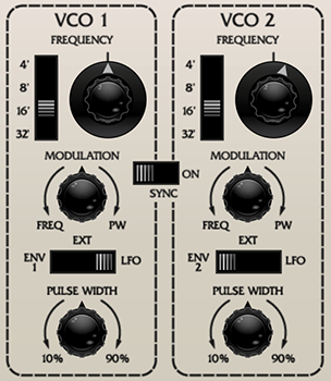
VCO 1 and 2
Synthesizer Expander Module includes two almost identical voltage-controlled oscillators. The only difference are their modulation routing options.
Range- Sets the pitch range for each oscillator in octaves. These are at standard organ footage settings of 32', 16', 8', and 4'.
Frequency knob- This can be used to fatten up two oscillator patches by detuning a small amount, or for "building-in" a set interval. Its range is a smidge over a fifth, up or down.
Modulation amount knob and source switch- The mod amount knob is bidirectional; rotating it left from center position adds pitch modulation, rotating it right modulates pulse width of the pulse wave. Center position is off, i.e. no modulation.
The three-position slide switch selects the oscillator mod source from three sources:
Env 1 (VCO 1) / Env 2 (VCO 2)- Modulation source is envelope 1 or envelope 2. Selecting the envelopes as mod source doesn't "disconnect" them from the VCA or VCF.
Ext- Enables CV mod from the Extmod In jack and attenuator. The attenuator is bipolar - center position is zero; turn right for positive CV or left for inverted (negative) CV values.
LFO- Enables mod from the onboard LFO.
Pulse Width- Sets the width or "duty-cycle" of the pulse wave. It has no effect on the saw wave. This defaults to 50%, i.e., a perfect square wave. Moving the knob left or right narrows its width as well as the thickness of sound until it almost disappears at its extremes.
Sync- This causes VCO 1 to force reset the start of VCO 2's waveform to the beginning of its cycle, resulting in a wide range of harmonic tones from VCO 2. The range of tones can be varied by adjusting VCO 2's Frequency controls.
Choosing oscillator waveforms- One unusual aspect of the Oberheim SEM design is that the oscillators themselves contain no waveform controls. Instead, the level of saw and pulse waves is adjusted via mixer knobs at the bottom of the VCF section.
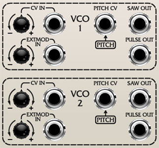
VCO 1 and 2 Patch Panel
Allows control of VCO frequency mod via patch cables routed from other modules, or the Synthesizer Expander Module itself, as well as separate wave outputs. All attenuator knobs are bipolar - center position is zero; turn right for positive CV or left for inverted (negative) CV values.
CV In jack and attenuator- Allows CV control of oscillator frequency.
Ext Mod In jack and attenuator- Allows CV control of oscillator frequency. Only active when the three-position modulation source switches in the VCO 1 and 2 sections are set to Ext.
If you need more mod inputs, remember that Voltage Modular allows an unlimited number of cables to be plugged into a single jack, or alternatively, you could mix all the mod sources with mixer module.
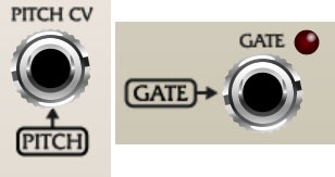
Pitch CV in jack and attenuator- Allows CV control of oscillator frequency. These are active at all times and are unaffected by the three-position modulation source switches in the VCO 1 and 2 sections. These are 1V/oct inputs, intended for half-step pitch control input from a keyboard controller or sequencer. If nothing is plugged in, the IO Panel Pitch output is normalled to the Pitch CV jack for pre-routed keyboard controller; plugging a jack into Pitch CV will disable the normalled routing.
The framed Pitch box indicates the normalled connection.
Saw Out jack- Direct out of the saw wave. This comes before the filter and amplifier stages.
Pulse Out jack- Direct out of the pulse wave. This comes before the filter and amplifier stages.
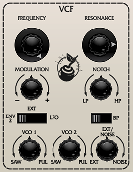
VCF
The Voltage Synthesizer Expander Module filter section represents a departure from the 24 dB "ladder" style filter often seen in vintage synths. Like the Oberheim SEM module it's based on, Cherry Audio's SEM module uses a 12 dB state-variable filter (no, this doesn't mean it can sound like Rhode Island or Montana). This refers to its curves - it can function as a lowpass, bandpass, or highpass filter and features a knob allowing a continuous sweep from lowpass to highpass response (with "notch" filtering in the middle position). This gives it a great deal of flexibility, and the 12 dB curve gives it a brighter overall tonality than a typical ladder filter.
If you're not familiar with how filters work, a lowpass filter allows frequencies below the cutoff frequency setting to pass through, but blocks frequencies above the cutoff frequency. Highpass is the opposite of lowpass mode: high-frequency content remains, but low frequencies are removed as the cutoff frequency increases. Sliding the Bandpass switch enables Bandpass mode combining both lowpass and highpass modes, leaving sound only "in the middle." The cutoff frequency lies roughly halfway between the falloff on each side. A notch filter does the opposite - it removes a middle piece of the audio spectrum but leaves other frequencies intact. (That might not sound useful, but setting the filter to Notch mode and slowly sweeping the cutoff frequency with an LFO creates nifty phaser-like tones - great for imitating vintage string synths.)
Frequency- Sets the frequency where frequency attenuation begins with its effect dependent upon the currently chosen lowpass/bandpass/notch/highpass/etc. filter mode.
Resonance- Emphasizes sound energy at and around the cutoff frequency by adding feedback from the filter's output back to its input. This is useful for creating commonly heard synth "wah" tones, especially when the cutoff frequency is modulated with an envelope generator or one of the LFO's.
Modulation amount knob and source switch- Applies modulation to the filter cutoff frequency. The mod amount knob is bidirectional; rotating it right from center position adds positive modulation, rotating it left adds negative modulation. Center position is off, i.e. no modulation.
The three-position slide switch selects the filter mod source from three sources:
Env 1 (VCO 1) / Env 2 (VCO 2)- Modulation source is envelope 1 or envelope 2. Selecting the envelopes as mod source doesn't "disconnect" them from the VCA or VCF.
Ext- Enables CV mod from the Extmod In jack and attenuator. The attenuator is bipolar - center position is zero; turn right for positive CV or left for inverted (negative) CV values.
LFO- Enables mod from the onboard LFO.
LP>HP/Notch control- Continuously varies the filter response from lowpass to highpass as the knob is rotated from left to right. The middle position creates a notch response.
BP (bandpass) switch- Alters the filter response to bandpass when engaged (i.e. combination of lowpass and highpass leaving frequencies "in the middle." The LP>HP knob disappears when the BP switch is enabled.
VCO 1 / VCO 2 Saw/Pulse level- The VCO 1 and VCO 2 knobs adjust the volumes of the saw and pulse waves for VCO 1 and 2, respectively. These are bidirectional knobs as well - rotating them left from center position increase the saw wave level, rotating it right increase the volume of the pulse wave. Center position is off (if you're getting no sound, check these first).
Ext/Noise level- When rotated to the left, this sets the level of signals plugged into the patch panel Ext Audio In panel jack, when rotated right, it sets the level of the onboard pink noise generator.
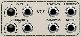
VCF Patch Panel
Allows control of VCF frequency mod via patch cables routed from other modules, or the Synthesizer Expander Module itself as well as outputs for all four filter responses. All attenuator knobs are bipolar - center position is zero; turn right for positive CV or left for inverted (negative) CV values.
CV In jack and attenuator- Allows CV control of filter cutoff frequency.
Ext Mod In jack and attenuator- Allows CV control of filter cutoff frequency. Only active when the three-position modulation source switches in the VCF section is set to Ext.
Lowpass / Highpass / Bandpass / Notch Out jacks- Separate outputs for each of filter responses. These are all available simultaneously - try routing a couple or all of them to a mixer, and play with their levels and the cutoff frequencies for all manner of awesome formant tonalities.
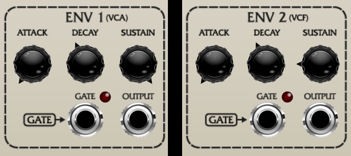
Envelope 1 and 2
The original SEM modules included two attack/decay/sustain (ADS) envelope generators. These function much the same as more common attack/decay/sustain/release (ADSR) envelopes, the only difference is that the decay and release stages are combined into a single control.
How They Work
When a voice sees a gate voltage from a note, the envelope outputs a dynamically changing voltage, according to the settings of its stages. The Attack stage defines how long it takes for the output voltage to rise from 0 to 5 volts. Once the Attack stage reaches 5V, it moves to the Decay phase. If the key is released, the Decay knob defines how it long takes for the voltage to fall back to zero. If the key is held, the Decay time defines how long it takes to fall to the Sustain level setting. The note then holds at the Sustain level until it is released, and fades to zero at the time set by Decay knob - the Decay knob effectively does "double-duty," acting as a decay and a release control.
Envelope Controls
Attack- Defines the length of time for voltage to rise from 0V to 5V when a key is played.
Decay- If the key is released, the Decay knob defines how it long takes for the voltage to fall back to zero. If the key is held, the Decay time defines how long it takes to fall to the Sustain level setting.
Sustain- Sets the voltage (i.e. the level) the envelope holds at following the Attack and Decay phases.
Envelope 1 and 2 Routing
As indicated on the front panel, Env 1 generally affects the VCA, i.e., amplitude. It's hard-wired to the VCA, so no other routing is necessary. If VCO 1's three-way mod routing switch is set to the Env 1 position, it will also modulate VCO 1's pitch.
Env 2 is mainly intended to modulate VCF cutoff frequency, but because it's not hard-wired, VCO 2's three-way mod routing switch needs to be in the Env 2 position for cutoff mod to occur. In addition to filter cutoff frequency, Env 2 can also be used to modulate VCO 2's pitch when VCO 2's three-way mod routing switch is set to the Env 2 position.
Envelope 1 and 2 Patching
Unlike the left-side CV inputs, these are in the same sections as the controls (space considerations!).
Gate in jacks and LED- This is where you'll patch gate voltages to initiate the envelope generator cycle. Most often this will come from the IO Panel Gate output. The LED's next to the gate jacks illuminate when a gate signal is present. If nothing is plugged in, the IO Panel Gate output is normalled to the Gate jack for pre-routed keyboard controller; plugging a jack into Pitch CV will disable the normalled routing.
The framed Gate box indicates the normalled connection.
Output- Envelope CV signal outputs.
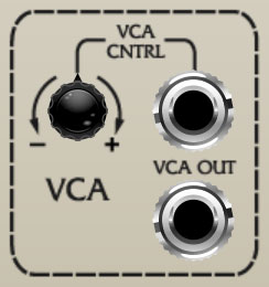
VCA
VCA switch- Synthesizer Expander Module's VCA has only one control, but it's important to understand. It's located in the middle, directly above the master Output knob. When set to Env 1 position, amplitude is controlled by envelope 1; this where you'll generally leave it when playing with a keyboard or sequencer controller. The On/Ext position latches the VCA open; this useful for drones or when using the Ext Audio In jack to process signals with the filter (this way you won't need to hold a key down to hear sound).
VCA Patch Panel
Allows control of VCA amplitude via CV's routed from other modules, or the Synthesizer Expander Module itself, and also includes an output. The attenuator knobs is bipolar - center position is zero; turn right for positive CV or left for inverted (negative) CV values.
VCA Control In jack and attenuator- Allows CV control of the amplitude level.
VCA Out- This is a VCA signal out. It's essentially the same as the master Output jack, but with no volume control.
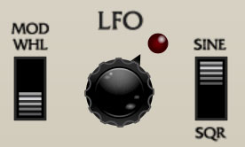
LFO
The LFO generates sub-audio range signals intended for modulation purposes.
Mod Wheel switch- Turning this on normals the IO Panel CV Sources/Mod Wheel output to LFO depth control. This makes setting up the LFO with a mod wheel super easy. If the Mod Wheel switch is on and your controller's mod wheel is at zero, the LFO won't have any signal output, thus... if the LFO doesn't seem to be working, make sure the Mod Wheel switch is in the off position (or push up your controller's mod wheel).
Frequency (control unlabeled)- The Rate knob sets the speed of the LFO, from 0.08 to 15 Hz (with Sync switch off) or from 8 beats up to 1/64th note triplets (Sync switch on). The LED beside it flashes at the current rate.
Wave Select- Chooses between sine and square waves.
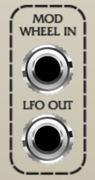
LFO Patch Panel
Mod Wheel In jack- The mod wheel is used to vary the depth of the LFO. The IO Panel Mod Wheel jack is normalled to LFO depth when the LFO section Mod Whl switch is in the up position; patching a cable to the Mod Wheel In jack overrides the IO Panel connection. Remember that the Mod Wheel In jack can accept a CV from any source, not just the mod wheel.
LFO Out jack- CV output of the LFO. You may not need it, because the LFO CV out is normalled to VCO 1 and VCO 2's mod routing switch, but patching a cable from the jack lets you route to other desinations in Synthesizer Expander or to external modules.
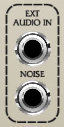
Ext Audio In and Noise Out Patch Panel Jacks
Ext Audio In- Routes audio to the filter inputs. To hear external audio, the Ext/Noise knob in the VCF section needs to dialed toward Ext.
The VCA switch (beneath the LFO section) is important when using the Ext Audio In jack. When set to Env 1, you'll only hear the external audio signal when a key is played (or the gate signal to Env 1 is high). Setting the VCA switch to On/Ext latches the VCA open so that external signals are always audible. This is useful when using the Synthesizer Expander's filter to process other signals such as drum loops, etc.
Noise- Direct output for the onboard pink noise generator.
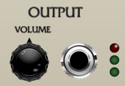
Output Section
Volume, output jack, and meter- This is post-VCA, and is the final module output with volume control. The red meter LED will glow when things are getting too hot. Note that this output is essentially the same as the output in the VCA patch panel section, but with a volume knob.
Disclaimer: Oberheim® and SEM are trademarks of Tom Oberheim. There is no association, affiliation or endorsement of Cherry Audio or its products by Tom Oberheim.