The Cherry Audio One To Eight Switch module routes an audio or control input signal to eight individual output jacks. Signal is only passed from an output when its respective “step” is active. The outputs can be stepped through sequentially with a manual or CV trigger, or targeted individually via discrete control voltages.
Switches are used to re-route signals without having to unplug or re-patch any cables. As an example, the One To Eight Switch could be used to pass a clean audio signal from one output while sending another output to a distortion module and another to a delay unit. The fun starts when you begin experimenting with different ways to step through the outputs!
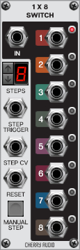
Inputs, Outputs and Controls
In jack- Input jack for the signal that will be routed to the eight outputs.
1-8 output jacks and LEDs- These eight jacks output the signal received at the input jack whenever their respective step is active. The small red LEDs give visual feedback of the active step.
Steps- Sets the number of steps that can be activated. When stepping through the outputs sequentially with either the manual or Step Trigger CV input, this sets the number of the last step before it will cycle back to step one.
Step Trigger jack- A 5V pulse or gate received at this jack will trigger the steps sequentially.
Step CV jack- CV input jack for switching between steps in any order. The control voltage range of 0V - 5V is evenly divided between the number of steps making it possible to target specific steps with discrete voltages.
Here are a couple examples of how the voltage is divided:
If Steps is set to two, the 5V range is divided between the two steps. Step one is selected with voltage from 0V - 2.49V and step two is selected with 2.5V - 5V.
If Steps is set to eight, the 5V range will be divided equally between the eight steps. Five divided by eight is 0.625 so, step one = 0V - 0.62V, step two = 0.63V - 1.24V, step three = 1.25V - 1.87V and so on.
If you don’t happen to make music with a calculator next to you, we recommend just playing around until you find the step you’re looking for!
Reset jack- A 5V pulse or gate received at this jack will immediately force the module back to step one. Note that resetting the module will be unnoticeable when using the Step CV input because the voltage received at its jack is constantly updating the active step.
Manual Step- Click this button to manually advance to the next sequential step.