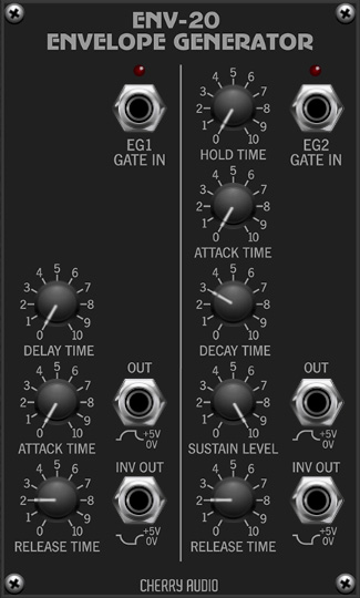
The EG-20 module replicates the dual envelope generators featured in the classic Korg MS-20 monosynth. In addition to their particular envelope curves and times, these include a couple of unique features.
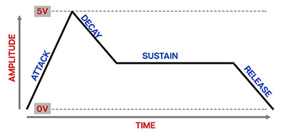
If you're not familiar with the operation of envelope generators, here's an overview of a standard ADSR-style envelope generator:
When a gate voltage is sent to the Gate In jack, the envelope generator outputs a voltage that changes dynamically according to the settings of its four stages.

The Attack stage defines how long it takes for the output voltage to rise from 0 to 5 volts. Once the attack stage reaches 5V, it moves to the Decay phase, which defines how long it takes to fall from 5V to the setting of the Sustain phase. Unlike the Attack, Decay, and Release phases, each of which define a time, Sustain simply sets the held voltage level following the Attack and Decay phases - this usually equates to the envelope output level while holding down a key on a keyboard controller. Finally, the Release knob defines the the length of time it takes for the voltage to fall back to 0V when the gate input voltage is removed (typically when you let go of a key on a keyboard controller).
Now that you're an ADSR envelope expert, let's go over the specifics of the EG-20 envelopes.
Inputs, Outputs, and Controls
EG-20 is a dual envelope generator; each envelope generator operates completely independently. Not only do they have different controls, their timing constants are different as well. We'll refer to the left side envelope as EG 1 and the right side one as EG 2.
EG1 / EG 2 Gate In jacks- This is where you'll patch gate voltages to initiate the envelope generator cycle. Most often this will come from the IO Panel Gate output. The standard gate voltage for Voltage Modular (and most hardware analog synths) is +5V, but EG-20 responds to gate voltages as low as +2.5V.
Can I use a "trigger" to trigger an envelope generator? It would seem logical, but the answer is, "sometimes, but generally, no." First let's clarify the difference between a gate signal and a trigger signal:
Most standard envelope generators need to see a constant gate voltage to move through the Attack and Decay phases and hold during the Sustain phase. Removing the gate voltage following the Sustain phase tells it to move to the Release stage. With all that in mind, using a trigger signal will typically cause the envelope generator to immediately jump to the Release phase. However, EG-20's EG 2 can move through multiple stages using by using the Hold Time knob - more on this below.
EG 1 / Delay Time- Delays the onset of the EG1's attack phase by up to about 10.5 seconds when gate is high.
EG 1 / Attack Time - Defines the length of time for voltage to rise from 0V to 5V when the gate voltage is applied. EG1 max attack time is 30 seconds (!).
EG 1 / Release Time- Defines the length of time for voltage to fall from 5V to 0V when gate/key is released.
EG 1 / Sustain switch- When turned on, following the attack stage, this holds the output voltage at 5V until the key is released.
EG 2 / Hold Time- Turning this up holds the gate high when a key is momentarily struck for up to 22 seconds. This allows EG 2 to run through its stages without the need to hold a key for the duration, and also allows very brief gates to be used (i.e. trigger signals).
EG 2 / Attack Time - Defines the length of time for voltage to rise from 0V to 5V when the gate voltage is applied. EG1 max attack time is 14 seconds.
EG 2 / Decay Time- Defines the length of time for voltage to fall from 5V to sustain level
EG 2 / Sustain Level- Sets the held voltage level of held notes following the decay stage.
EG 2 / Release Time- Defines the length of time for voltage to fall from sustain level to 0V when gate is released.
Env Out (top) / Inv Out- These are the envelope voltage outputs. The Out voltage ranges from 0V to +5V. The Inv Out jack is a bit unusual - instead of outputting voltage from 0 to -5V, its output ranges from +5V to 0V. This mimics the functionality of the original MS-20 envelopes.